Page 5
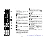
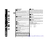
MONITOR SENDS
These controls route the input channel signal to any one or more Monitor
busses and the associated Monitor Outputs, allowing a number of unique
monitor mixes to be created. The sends are arranged as a group of mono
sends (1-8) and two stereo pairs (9/10 & 11/12). Each group of sends is
normally POST-FADE, POST-EQ but may be switched to PRE-FADE,
POST-EQ by pressing the corresponding PRE switch. All sends are muted
when the MUTE switch (9) is pressed. Sends 9-12 are arranged as two
stereo pairs, with a send level control and a PAN control to position the
channel signal in the stereo image. With the PAN control centered, the
signal is fed equally to both sends in the pair. You get most control when the
input Sensitivity is set up correctly, giving maximum travel on the send
controls. See the `Setting Up & Troubleshooting section on page 8 for help
in setting a suitable signal level.
MUTE
All monitor sends are disabled when the MUTE switch is down, and the
associated amber LED illuminates to show that the switch is pressed.
FADER
The FADER provides overall level control of any Monitor Sends which are
selected as post-fade. You get most control when the input Sensitivity is set
up correctly, giving full travel on the fader. See the `Setting Up &
Troubleshooting section on page 8 for help in setting a suitable signal level.
SIGNAL LED
This green LED illuminates to show that a signal with a level greater than
-20dB is present in the channel.
PFL/PEAK
When the latching PFL switch is pressed, the pre-fade, post-EQ signal is fed
to the headphones and engineers wedge outputs, replacing the selected
wedge source and illuminating the SOLO/PFL LED on the Master section to
show that a PFL is active. The adjacent red LED lights to identify the
selected channel. This is a useful way of listening to any required input
signal without interrupting any of the monitor sends, for making
adjustments or tracing problems.
When the PFL switch is released the LED serves as a PEAK indicator which
illuminates approximately 4dB before clipping to give warning of a possible
overload. The signal is sampled at two points in the EQ section and at the
Insert Send.
7
9
10
12
11
8
www.audiovias.com
Содержание SoundCraft MONITOR 2
Страница 1: ...Featuring www audiovias com...
Страница 2: ...www audiovias com...
Страница 4: ...Page 3 INPUTS 24 Connecting Up www audiovias com...
Страница 10: ...Page 9 BAND INSTRUMENTS VOCALS Live Monitor with Effects APPLICATIONS www audiovias com...
Страница 11: ...BAND INSTRUMENTS VOCALS Page 10 Live Monitor with In Ear Monitoring www audiovias com...
Страница 12: ...2 CA Theatre www audiovias com...
Страница 13: ...2 CA FOH Console www audiovias com...
Страница 14: ...2 CA FOH Console with Subgrouping www audiovias com...
Страница 18: ...2 CA INPUTS MONITOR 2 CONSOLE Typical Starting Out Control Positions www audiovias com...
Страница 20: ...A Harman International Company Part No ZM0192 Part No ZM0192 02 www audiovias com...

