


16
3-90-08101R23_06/13
wall Control wiring
The Wall Control sends and receives information from the
control board through a 4 wire Datacom cable. There is a 100’
length of this cable supplied with the furnace. 100’ lengths of
this cable can also be ordered separately, part #3-20-02583.
Alternately, any Datacom cable -CAT3- 2 twisted pair 24ga
solid wire can be acquired at a local electrical supply house.
Also any CAT3-24ga. solid wire 2, 3, or 4 pair cable can be
used because they all have the same pair color combinations.
The maximum length of wall control wiring is 100 feet.
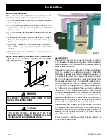
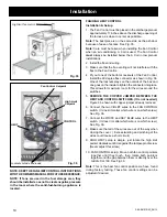
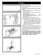
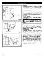
The furnace connecting point is a 4 pole screw terminal block
on the side of the hopper just around the corner to the right
of the control. Follow the wiring instructions on the label
alongside the terminal block. See Fig. 31.
CAuTION:
With this small gauge of wire, care must be taken
not to overtighten the terminal screws thus, breaking the wire.
There are tie-wrap holes in the face of the hopper aprox.
every 6” to keep the cable secure and out of the way.
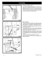
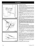
The Wall Control is made to fit on a standard wall case
electrical box. It could also be mounted directly to a stud
using 2 drywall screws. In either case the screws should be
turned in and tested for a snug fit when the Wall Control is
slid down over the screws. The Wall Control only hangs on
the screws so a good fit is important.
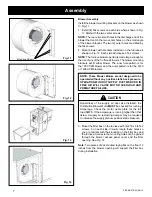
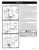
Remove the Wall Control and make the Datacom cable
connections with the UY auto splicers provided.
dO NOT
STrIP ThE wIrES
. Following the wiring diagram on the
inside of the Wall Control make each splice. See Fig. 32.
Insert the two matching color wires fully into the two holes
of one of the UY connectors. A pair of standard Channel-
lock pliers works ideally to squeeze the raised button down
into the UY connector body. Extra UY connectors can be
purchased. Part # 3-20-00200
NOTE:
A pair of needle nose pliers may be helpful to insert
the BLUE T-stat wires fully into the connector. Visually inspect
to see that the wires are fully inserted before squeezing the
UY splicer.
Installation
Orange - Red (+ LED )
Orange/White - White or Black ( - LED)
Blue - Blue ( Tstat )
Blue/White - Blue ( Tstat )
Datacom Wall Control
Cable
Fig. 32
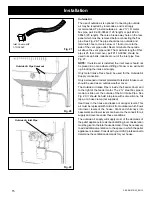
Fig. 30
Fig. 31
Содержание PF100
Страница 48: ...48 3 90 08101R23_06 13 ...


