


11
676
TU B E M I C
CHAN N E L STR I P
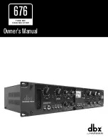
EQ Example Settings
The below settings are designed to be used as a starting point. Your results using these settings will vary depending on the
variables inherent in your application. For best results, adjust the settings to suit your application as described in the section
following the below examples.
LEAD VOCALS
ACOUSTIC GUITAR
MIKED ELECTRIC GUITAR
DIRECT BASS GUITAR
PEAK
EQ
ENABLE
COMP/LIM
ENABLE
NARROW
CONTOUR
SIDECHAIN
ENABLE
OVEREASY
DIGITAL
OUTPUT
POWER
|
20dB
PAD
+48V
POLARITY
INVERT
80 Hz
LOW CUT
+
0
–
PEAK
LIMIT
GAIN
dB
+55
+25
+50
+40
-
∞
POST TUBE
ATTENUATION
dB
-
∞
0
-30
-5
-15
LOW
dB
-15
+15
0
MID
dB
-15
+15
0
HIGH
dB
-15
+15
0
AUTO
RELEASE
dB/sec
4k
10
400
1.5k
70
ATTACK
dB/msec
400
80
200
10
1
LIMITER
dBu
RED: 96kHz
GREEN: 48kHz
YELLOW: 44.1 kHz
-4
+2
+18
+10
OFF
THRESHOLD
dB
-40
0
+20
-10
-20
-30
+10
RATIO
1:1
∞
:1
1.5:1
3:1
2:1
1.2:1
8:1
MAKEUP
GAIN
dB
-20
+20
0
-10
+10
INSTRUMENT INPUT
ENABLE
CLAS
S “
A
” V
A
CU
U
M TU
B
E WITH H
IG
H V
OL
TA
G
E GAI
N
METER SELECTION
INPUT
OUTPUT
G.R.
FREQ
Hz
1k
100
8k
200
2k
PEAK
EQ
ENABLE
COMP/LIM
ENABLE
NARROW
CONTOUR
SIDECHAIN
ENABLE
OVEREASY
DIGITAL
OUTPUT
POWER
|
20dB
PAD
+48V
POLARITY
INVERT
80 Hz
LOW CUT
+
0
–
PEAK
LIMIT
GAIN
dB
+55
+25
+50
+40
-
∞
POST TUBE
ATTENUATION
dB
-
∞
0
-30
-5
-15
LOW
dB
-15
+15
0
MID
dB
-15
+15
0
HIGH
dB
-15
+15
0
AUTO
RELEASE
dB/sec
4k
10
400
1.5k
70
ATTACK
dB/msec
400
80
200
10
1
LIMITER
dBu
RED: 96kHz
GREEN: 48kHz
YELLOW: 44.1 kHz
-4
+2
+18
+10
OFF
THRESHOLD
dB
-40
0
+20
-10
-20
-30
+10
RATIO
1:1
∞
:1
1.5:1
3:1
2:1
1.2:1
8:1
MAKEUP
GAIN
dB
-20
+20
0
-10
+10
INSTRUMENT INPUT
ENABLE
CLAS
S “
A
” V
A
CU
U
M TU
B
E WITH H
IG
H V
OL
TA
G
E GAI
N
METER SELECTION
INPUT
OUTPUT
G.R.
FREQ
Hz
1k
100
8k
200
2k
Setting The EQ
1�
Engage the
EQ ENABLE
button.
2�
While monitoring the source signal, adjust the
LOW
and
HIGH
knobs to tailor the low and high frequencies to your liking.
3�
To adjust midrange frequencies, set the
MID
control to around the 3 o’ clock position or until the boost is quite noticeable.
4�
Sweep the
FREQ
control until you locate the mid frequencies you wish to alter.
5�
Set the
NARROW
button to the desired setting. For example, engage the
NARROW
button for applications where you
want to affect less of the surrounding frequencies (such as when removing the low-mid mud from distorted electric
guitars but want to retain the low-end body of the tone). Disengage the
NARROW
button for a broader, more natural
sounding filter – for example, when boosting to add focus to the source.
6�
Adjust the
MID
control for the desired amount of boost or cut.
7�
Audition the signal and try engaging and disengaging the
NARROW
button one more time to see which setting gets you
closer to the desired sound.
8�
Re-adjust the
POST TUBE ATTENUATION
control if necessary. For example, if you have applied ample amounts of
EQ boost, the input PEAK LED may light, indicating that you need to lower the
POST TUBE ATTENUATION
control.
Conversely, if you have applied ample amounts of EQ cut, you may want to raise the
POST TUBE ATTENUATION
control
to compensate. In most cases, when applying subtle EQ, no adjustment or very little adjustment may be necessary.
Содержание dbx 676
Страница 1: ...Owner s Manual 676 TUBE MIC CHANNEL STRIP...
Страница 30: ...28 676 TUBE MIC CHANNEL STRIP Specifications TBD...