

QUICK START GUIDE
NX-2200
NetLinx NX Integrated Controller
Overview
This guide pertains to the NX-2200 NetLinx NX Integrated Controller (
FG2106-02
). The
purpose of this document is to illustrate how to set up the device in its simplest
configuration. Additional Documentation for this device is available at www.amx.com:
• Refer to the
NX-x200 Series Hardware Reference Guide
for additional details on
installing, upgrading, and wiring the NX-2200.
• Refer to the
NX Series NetLinx Integrated Controllers WebConsole & Programming
Guide
for detailed configuration instructions.
• You can access this Quick Start Guide online by using your mobile device to scan
the QR code located on the bottom of the NX-2200.
What’s in the Box?
The following items are included with the NX-2200:
• 1 2-pin 3.5 mm mini-Phoenix (female) PWR connector
• 1 4-pin 3.5 mm mini-Phoenix (female) AxLink connector
• 1 6-pin 3.5 mm mini-Phoenix (female) I/O connector
• 1 10-pin 3.5mm mini-Phoenix (female) RS232/422/485 connector
• 3 5-pin 3.5mm mini-Phoenix (female) RS232 connectors
• 2 CC-NIRC, IR Emitters (
FG10-000-11
)
• 2 removable rack ears
Environmental Requirements
The environmental requirements for the NX-2200 are as follows:
•
Operating Temperature
: 32° F (0° C) to 122° F (50° C)
•
Storage Temperature
: 14° F (-10° C) to 140° F (60° C)
•
Operating Humidity
: 5% to 85% RH
Modes and Front Panel LED Blink Patterns
The following table lists the modes and blink patterns for the front panel LEDs
associated with each mode. These patterns are not evident until after the unit is
powered.
Getting Connected
NOTE: Ensure the PC you are using to connect to the controller has the latest version of
NetLinx Studio 4.0 installed on it.
Once the controller is powered on, you can connect to it through its IP address.
NOTE: NX-Series controllers fully support IPv6 network addressing. If the LAN port is
connected to an IPv6 capable network it will self select an appropriate IPv6 address
based on the discovered address parameters of the network to which it’s attached.
Connecting to the NX-2200 over Ethernet
The NX-2200 is configured for DHCP addressing by default. The controller uses link
local addressing as a backup in case the DHCP server is inaccessible. See the
Changing
the IP Address section
for information on setting a static IP address. Verify there is an
active LAN connection on the controller’s LAN port before beginning this procedure.
1.
Using category cable, connect the LAN port on the rear panel of the controller to
your external network.
FIG. 1 displays the location of the LAN port on the rear panel.
FIG. 1
NX-2200 REAR PANEL
2.
In NetLinx Studio, select
Settings > Workspace Communications Settings
to
open the Workspace Communication Settings dialog.
3.
Click
System Settings
to open the Communication Settings dialog, and select the
Network
tab.
4.
Click
Listen for Masters
to open the Listen For Masters dialog, and click
Start
Listening
to begin listening for “blink” (UDP) messages from NetLinx Masters on
the same subnet. As Masters are discovered, they are added to the List of Active
NetLinx Master Controllers.
5.
When you see the IP Address for the target Master in the List of Active NetLinx
Master Controllers, click
Stop Listening
.
6.
Select the IP Address of the target Master and click
Select to Add
. The New TCP/
IP Setting dialog appears, indicating the selected IP address. Fill in the available
fields as necessary. Click
OK
to save changes and return to the Communication
Settings dialog. The new Master’s IP address now appears in the List of
Addresses.
7.
With the newly added Master selected, click
Select
. The window updates to
indicate that the newly added and selected Master is now the current
communication configuration.
8.
Click
OK
on each open dialog to exit and return to the workspace.
9.
Refresh the Online Tree (select
Refresh System Online Tree
from the Online Tree
context menu) to connect to the Master.
Connecting to the NX-2200 via USB
If you do not have a DHCP server or if the controller has an unknown static IP address,
you obtain the IP address of the controller via USB.
1.
Using a standard Type-B to Type-A USB cable, connect the Program Port on the
front panel of the controller to your PC.
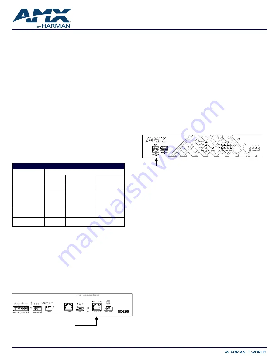
FIG. 2 displays the location of the Program Port.
FIG. 2
NX-2200 FRONT PANEL
2.
Select
Settings
>
Workspace Communications Settings
to open the Workspace
Communication Settings dialog.
3.
Click
System Settings
to open the Communication Settings dialog.
4.
Select the USB tab. The USB tab features a list of Masters connected to your PC
via USB. The IP address of the Master appears in the IPv4 Address column.
5.
Highlight your Master and click
Select
to connect to it.
Switching the IP Address from a Dynamic to Static
To toggle between static and dynamic IP addresses, hold the ID pushbutton on the front
panel of the NX-2200 for 10 seconds. When complete, the controller automatically
reboots itself. After the controller is fully booted, use the Workspace Communications
Settings dialog in NetLinx Studio to create a new connection to the controller. See the
Default IP Addresses section
for the list of default IP addresses.
NOTE: Ensure the controller is fully booted when you press and hold the ID pushbutton.
Pressing and holding the ID pushbutton while the controller is booting resets the unit to
its factory defaults.
Changing the IP Address Once You Are Connected
Perform these steps to change the IP address once you are connected to the controller:
1.
Set the IP address on your PC to the same network the controller is currently on.
2.
In NetLinx Studio, select
Diagnostics > Network Addresses
from the menu bar to
open the Network Addresses dialog.
3.
Click
Get IP Information
to enable the fields for editing.
4.
Enter the System, Device (0 for NetLinx Masters), and Host Name information.
5.
To specify a network IP address, select
Specify IP Address
.
6.
Enter the IP parameters into the available fields.
7.
Click
Set IP Information
to retain the pre-reserved IP Address to the Master.
8.
Click
Reboot Device
to finish assigning the IP address to the Master, and click
OK
to close the dialog.
MODES AND LED BLINK PATTERNS
LEDs and Blink Patterns
Mode
STATUS
(green)
OUTPUT
(red)
INPUT
(yellow)
Boot
ON
OFF
ON
Contacting DHCP
server
ON
OFF
Fast Blink
Using link-local
address
Slow Blink
OFF
OFF
Program running
Slow Blink
ON when
transmitting data
ON when receiving
data
No program running
ON
ON when
transmitting data
ON when receiving
data
Connect category cable
to the LAN port
Connect Type-B USB cable
to the Program Port


