

© 2016 Harman. All rights reserved. Hydraport, AMX, AV FOR AN IT WORLD, HARMAN, and their respective logos are registered trademarks of
HARMAN. Oracle, Java and any other company or brand name referenced may be trademarks/registered trademarks of their respective
companies.
AMX does not assume responsibility for errors or omissions. AMX also reserves the right to alter specifications without prior notice at any time.
The AMX Warranty and Return Policy and related documents can be viewed/downloaded at www.amx.com.
3000 RESEARCH DRIVE, RICHARDSON, TX 75082 AMX.com | 800.222.0193 | 469.624.8000 | +1.469.624.7400 | fax 469.624.7153
AMX (UK) LTD, AMX by HARMAN - Auster Road, Clifton Moor, York, YO30 4GD United Kingdom • +44 1904-343-100 • www.amx.com/eu/
93-0552-32 REV: B
Last Revised: 9/21/2016
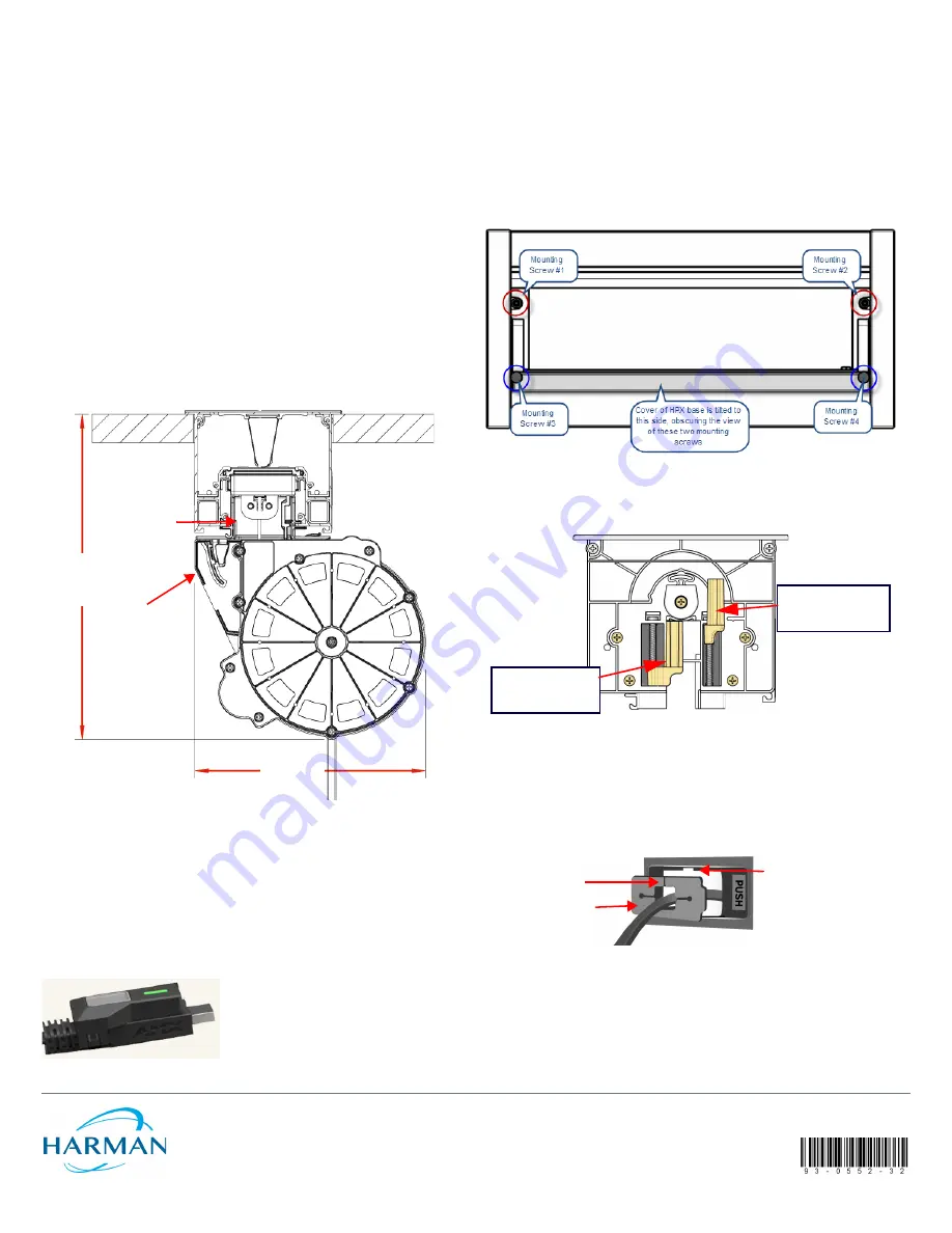
Mount the HPX into the Mounting Surface
Caution: Do not use a high-powered torque screw driver. Over-tightening these screws
can damage the product.
Note:
For detailed instructions on installing the HPX base assembly, refer to the HPX-
600/900/1200 and HydraPort Touch (7”/10”) Installation Guides (available online at
www.amx.com).
1.
Carefully insert the HPX base into the cutout in the mounting surface.
2.
Tighten the four mounting screws (FIG. 8) located inside and at each end of the
HPX base assembly, to rotate the retaining tabs (FIG. 9) into locking position
under the mounting surface.
3.
Minding the twist in the cable
, feed the excess cable up through the mounting
collar and insert the cable cartridge hook into the mounting collar cutout.
Note:
If a twist in the cable occurs from rotating the cassette before insertion, the
cable will bind and will not fully retract.
4.
Push the cable cartridge trigger up onto the mounting collar tongue until it
latches (opposite of FIG. 4).
5.
Use the Push button to retract the cable into the cartridge.
6.
Attach the display ends of the cables as necessary and use cable ties to secure
cable bundles as necessary.
Mounting Dimensions
FIG. 6 provides dimensions for the retractable cable module, when installed in an HPX-
600/900/1200 and HPX-MSP-07/10 base assembly.
Optional MyTurn™ Source Selector Button
For customers who purchase the optional HPA-MYT-TX MyTurn™ Source Selector
Button (FG554-21), it clips into the specially designed groove built into the end of a
MyTurn ready cable. Users press the button to send content on their device to the
display. When pressed, the button transmits a signal to an optional receiver (FG554-23)
that plugs directly into an AMX switching device, such as a Solecis SDX, Enova DVX, or
NX Series Controller.
MyTurn Source Selector Buttons are illuminated briefly when that specific device is
selected, making it easy to determine whose content is being shown on the display at
any given time. Refer to the HPA-MYT-TX documentation available at www.amx.com for
more details.
Existing Installations
For existing HPX installations, the HPX Base Assembly must be removed from the table
surface before the Retractable Cable Modules can be installed:
Note:
It may be necessary to reorient existing 1st generation RCMs in the chassis to
ensure they fit against the non lip edge of MyTurn-Ready 2nd generation RCMs.
Otherwise a 1/2 M blank panel (FG558-01) or other non retractable cable module needs
to be installed between the 1st Generation and MyTurn-Ready 2nd Generation RCMs.
1.
Cut/remove any cable ties that would restrict the removal of the HPX Base Assembly.
2.
Loosen four mounting screws inside and at each end of the HPX base assembly
(FIG. 8), in order to rotate the retaining tabs from under the mounting surface.
Note:
When the cover of the HPX base is open, only two of these screws are visible.
To access the other two screws, tip the cover over to the opposite open position.
3.
Once the retaining tabs have been rotated out from under the mounting surface,
the HPX assembly can be lifted away from the mounting surface.
FIG. 9 provides a cutaway view of the End Cap, showing the retaining tabs
highlighted in both the loose position and the tightened (secure) position.
4.
Return to the installation section at the bottom left column of page 1 to continue
with installing the RCM into the HPX Base assembly.
Replacing MyTurn Ready
RCMs
Removal of the HPX Base assembly is not required to replace this RCM:
1.
Detach the cable cartridge from the mounting collar (FIG. 4).
2.
From the top of the mounting collar, press a small flat blade screwdriver into the
notch on the split side of the pop out panel and pop it out of place (FIG. 10)..
3.
Slip the cable out through the mounting collar.
4.
Replace with new RCM in reverse order ensuring the cable is not twisted and the
pop out panel split is oriented towards the notch in the collar.
Additional Documentation
Refer to the
Products > Architectural Connectivity
catalog page on
www.amx.com
(
Dealer Site
) for additional product documentation.
FIG. 6
RCM MODULE (INSTALLED IN AN HPX BASE) - DETAILED DIMENSIONS
FIG. 7
OPTIONAL MYTURN™ SOURCE SELECTION BUTTON (FG554-21)
5 ft Cable Pigtail
HPX Base Assembly Top
Mounting Surface Top
Removable RCM
cable cartridge
mounted to
(285.3 mm)
11.2 inches maximum
(202.5 mm)
8 inches
Removable RCM
mounting collar
mounted to HPX
Base
mounting collar
FIG. 8
HPX BASE ASSEMBLY (SHOWN MOUNTED) - MOUNTING SCREWS LOCATIONS
FIG. 9
HPX BASE ASSEMBLY (SHOWN MOUNTED) - MOUNTING SCREWS LOCATIONS
FIG. 10
RCM MOUNTING COLLAR POP-OUT PANEL
Right retaining tab
(to secure the unit)
shown tightened
Left retaining tab
(to remove the unit)
shown loosened
Mounting Collar
Pop-out panel
Slip cable through
slot in panel
Notch in Collar used to
pop out panel


