Installation and Setup
30
Hardware Reference Manual – DXLink™ Twisted Pair 4K Transmitters/Receivers
Wallplate Transmitters – Attaching Signal/Transport Cables
To attach signal and transport cables to a Wallplate Transmitter:
1.
Install standard US single-gang back box.
2.
Attach a twisted pair cable from the DXLink Input Board on the switcher to the DXLink (RJ-45) connector on the rear of the
unit.
3.
Attach unit to the back box with four screws through the large screw holes.
4.
Check LEDs for normal display (see the table below).
5.
Attach standard decor style front cover plate (customer provided) to the unit.
6.
Attach the HDMI cable from the source device to the HDMI In connector.
7.
Check LEDs for normal display (see the table below).
4K HDMI Wallplate TX – Indicator LEDs
The 4K HDMI Wallplate TX receives power from a switcher through the DXLink (RJ-45) connection to a DXLink Input Board in the
switcher. It can also receive power via either PDXL-2 (FG1090-170) or PS-POE-AT-TC (FG423-84).
IMPORTANT:
If the indicator LEDs do not respond with a normal display as stated in the table above, check all of the connections
before contacting technical support (see page 63).
Receiver Modules – Attaching Signal and Control Cables
IMPORTANT:
Before attaching cables, be sure to set DIP switch’s toggles if necessary (see page 27).
IMPORTANT:
Do not use th
e RJ-45 connector labeled “DXLink” for
connecting to a standard Ethernet Network.
NOTE:
Power, IR, and RS-232 ports are covered in their own sections.
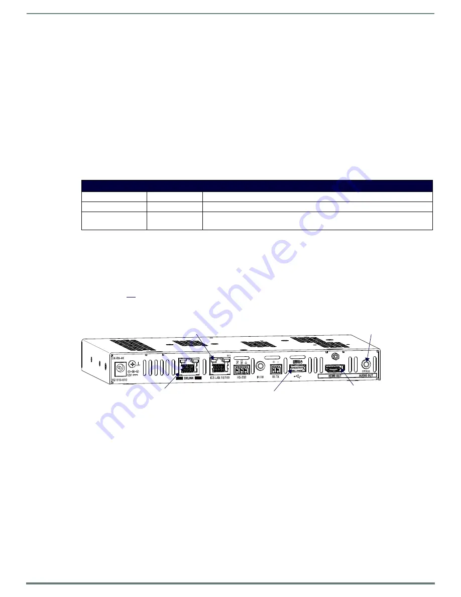
To attach signal, transport, and control cables to a DXLink Receiver:
1.
DXLink (input) connector – Attach a twisted pair cable from the switcher (or DXLink Transmitter) to the DXLink connector on
the Receiver.
2.
HDMI Out connector – Attach the HDMI cable that goes to the destination device.*
3.
ICS LAN 10/100 connector (optional) – Attach a twisted pair cable from this connector to a LAN. (For NetLinx programming
information, see page 47.)
4.
USB port (optional) – Connect to a hub using a USB-A cable; connect keyboard and mouse to the hub. (This port is for
sending keyboard / mouse commands to a PC.) For USB port information, see page 13. For USB SEND_COMMAND
information, see page 57.
5.
Stereo Audio Out connector (optional) – Plug the audio cable (that goes to the audio destination) into the stereo audio jack.
For audio precedence information, see page 29. For information on audio SEND_COMMANDs (including enabling the analog
audio format), see page 52.
* DVI cable can be used (via a DVI-to-HDMI cable adapter); however, the advanced audio support from HDMI will not be available.
NOTE:
The ID Pushbutton places the Receiver in ID Mode for setting the NetLinx ID (device only) and provides additional functionality,
such as placing the device in Static IP Mode or DHCP Mode. For information, see page 40.
TIP:
If scaling adjustments are necessary, use SEND_COMMANDs (see page 47). If connected to an Enova DGX output, consult the
switcher’s manual for scaling options.
4K HDMI Wallplate TX Indicator LEDs
LEDs
Normal Display
Indicates
DXLink
ON
DXLink connection is established
HDCP
Solid or Blinking
Solid: Present signal is HDCP encrypted
Blinking: Present signal is not HDCP encrypted
FIG. 18
Attach signal and control cables to the Receiver (DX-RX shown)
USB port
HDMI Out
DXLink input port
Stereo Audio Out
ICS LAN 10/100 port


