background image

ShadowLight XL

Direct Vent Gas Fireplace Insert

Owners Manual

WARNING: 

 If the information in this manual is not followed 

exactly, a fire or explosion may result causing property 

damage, personal injury or loss of life. 
Installation and service must be performed by a qualified 

installer, service agency, or the gas supplier. 
Do not store or use gasoline or other flammable vapors 

and liquids in the vicinity of this or any other appliance.
FOR YOUR SAFETY:   

WHAT TO DO IF YOU SMELL GAS 
• Do not touch electrical switches.
• Do not try to light any appliance.
• Open windows.
• Extinguish any open flame.
• Do not use the phone in your building.
• Immediately call your gas supplier from a neighbor's 

phone. 
• Follow the gas supplier's instructions.
• If you cannot reach your gas supplier, call the fire 

department. 

ADVETISSEMENT: 

  Quinconque  ne  respect  pas  à  la 

lettre les instructions dans le présent manuel risque de 

déclencher un incendie ou une explosion entraíant des 

dommages matérials, des lésions corporelles ou la perte 

de vies humaines. 
L’installation et service doit être exécuté par un qualifié 

installer, agence de service ou le fourmisseur de gaz.
Ne pas entreposer ni utiliser d'essence ni d'autres vapeurs 

ou liquides inflammables dans le voisinage de cet appareil 

ou de tout autre appareil.
POUR VOTRE SÉCURITÉ: Que faire si vous sentez une 

odeur de gaz:
• Ne pas tenter d'allumer d'appareil.
• Ne touchez à aucun interrupteur. Ne pas vous servir 

des  téléphones  se  trouvant  dans  le  batiment  où  vous 

trouvez.
• Evacuez la pièce, le bâtiment ou la zone.
• Appelez immédiatement votre fournisseur de gaz depuis 

un voisin. Suivez les instructions du fournisseur.
• Si vous ne pouvez rejoindre le fournisseur de gaz, ap-

pelez le service dos incendies.

Tested by Intertek Testing Services/Warnock Hersey; 8431 Murphy Drive, Middleton, WI 53562

R2

8/06

Part #3-90-00395

Содержание ShadowLight XL

Страница 1: ...e respect pas à la lettre les instructions dans le présent manuel risque de déclencher un incendie ou une explosion entraíant des dommages matérials des lésions corporelles ou la perte de vies humaines L installation et service doit être exécuté par un qualifié installer agence de service ou le fourmisseur de gaz Ne pas entreposer ni utiliser d essence ni d autres vapeurs ou liquides inflammables da...

Страница 2: ...oisinage de cet appareil ou de tout autre appareil In the Commonwealth of Massachusetts this product must be installed by a licensed Massachusetts Plumber or Gas Fitter IMPORTANT The Shadowlight XL is manufactured and shipped set up for LP gas Propane Conversion kits page 14 are available to convert to natural gas or back to LP gas It is important to mark the fuel label accordingly so that the val...

Страница 3: ...13 Converting to Natural Gas 15 Converting to High Altitude 17 Venting 18 Installing into a Fireplace 20 Options 24 MAINTENANCE 25 Removing the Glass 25 Replacing the Gasket 25 Cleaning the Glass 25 Cleaning the Log Set and Firebox 25 Convection Blower Service Access 26 WIRING DIAGRAM 27 PARTS LIST 28 TROUBLE SHOOTING 30 WARRANTY 34 TABLE OF CONTENTS 3 ...

Страница 4: ...pplied by the manufacturer shall be used to convert this room heater to the alternate fuel Pour utilisation avec le gaz naturel et le propane Une trousse de conversion fournie par le fabricant doit etre utilisee pour passer d un combustible a l autre Keep burner and control compartment clean See installation and operating instructions accompanying appliance S assurer que le bruleur et le compartim...

Страница 5: ...Specifications 40 30 Front View Minimum Opening Size 29 Inlet Outlet Top View Side View Front View 14 13 5 ...

Страница 6: ...i Low Knob On Off Pilot Knob Igniter Blower Speed Switch On Off Thermostat Switch Pilot Glass Door Latch Handle Leveling Bolt Leveling Bolt Burner Plate Burner Lighting Instructions Safety Label Face Bolt Face Bolt 6 ...

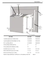
Страница 7: ...g Btu hr 2000 4500ft 610 1375m 34 000 BTU 34 500 BTU Min Input Rating Btu hr 21 600 BTU 20 900 BTU Orifices DMS 0 2000 ft 0 610m 31 50 Orifices DMS 2000 4500ft 610 1375m 33 51 Manifold Pressure in w c kPa 3 5 87 10 0 2 49 Minimum Manifold Pressure in w c kPa 1 3 32 3 6 0 9 Minimum Inlet Pressure in w c kPa 5 0 1 25 11 0 2 74 Maximum Output BTU hr 0 to 4 500 ft 0 to 1 375 m Blower off 27 600 28 600 7...

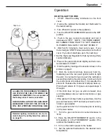
Страница 8: ...he Handles Lift bottom grill with index finger and fold down to access controls ON OFF THERMOSTAT Switch UP ON MIDDLE OFF DOWN THERMOSTAT ON OFF THERMOSTAT Pilot Location Shown Above Pull lighting instruction plate out to view text Push back in before closing grills Blower Speed Switch Piezo Igniter Button 8 ...

Страница 9: ...ral times before the pilot ignites Continue to hold the control knob in for about one 1 minute after the pilot is lit Release the knob and it will pop back up Pilot should remain lit If it goes out repeat steps 5 through 9 If the knob does not pop up when released stop and immediately call your service technician or gas supplier If the pilot will not stay lit after several tries turn the gas contr...

Страница 10: ...R SHUTTER ADJUSTMENT The adjuster can be accessed with a phillips screw driver just above the valve Turn the adjuster clockwise to increase flame height and counterclockwise to de crease See above left Adjusting the flames too high will cause them to have black tips and cause sooting Sooting can cause the glass to get dirty Warning The unit and adjuster may be hot Wear gloves and arm protection if m...

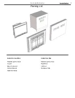
Страница 11: ...nly For Qualified Installers Packing List Inside the Insert Box ShadowLight XL Insert Log set Bag of rock wool Owners Manual Restrictor Plates Inside Face Box ShadowLight XL Face Right Door Left Door Hardware Pack 11 ...

Страница 12: ...near the ShadowLight XL Surveiller les enfants Garder les vêtements les meubles l essence ou autres liquides à vapeur inflammables lin de l appareil CLEARANCES The following clearances to combustibles must be observed Unit to mantel 8 or smaller or combustible trim unprotected 13 305 mm In addition to these clearances adequate acces sibility clearance for servicing and proper operation must be main...

Страница 13: ...RATING Gas Pressure Requirements Correct gas pressure and the use of a properly sized gas supply line are essential for the safe and ef ficient performance of this appliance Make sure that the plumber or gas supplier checks the gas supply line and gas pressure at installation NOTE Improper gas pressure can affect heater performance flame color or cause pilot outage Natural Gas Maximum inlet pressure...

Страница 14: ...gence qualifiee de service conformement aux instruc tions du fabricant et toutes exigencies et codes appli cables de l autorises avoir la jurisdiction Si l information dans cette Instruction n est pas suivie exactement un feu explosion ou production de protoxyde de carbone peut resulter le dommages causer de propriete perte ou blessure personnelle de vie L agence qualifiee de service est esponsable ...

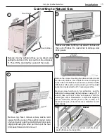
Страница 15: ...Using one hand gently push the side brick relief door open slightly and using the other pull the top of the rear brick panel forward and remove it Remove the screws mounting the intake air deflector and lift it from the firebox Next locate the screw holding the burner tube to the firebox floor and remove it Now the 50 LPG burner orifice can be removed using a 1 2 deep well socket and replaced with a 31...

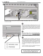
Страница 16: ...er box on the fuel label with a permanent marker Note If no conversion is made the box for propane must still be marked 7 Safety Label Use soap and water and or a gas detector to check for leaks before lighting the pilot 8 When installation has been completed verify the gas inlet and manifold pressures are within specifications The safety label located inside the bottom of the unit will have the in...

Страница 17: ...the rear brick panel Using one hand gently push the side brick relief door open slightly and using the other pull the top of the rear brick panel forward and remove it Remove the screws mounting the intake air deflector and lift it from the firebox Next locate the screw holding the burner tube to the firebox floor and remove it Now the burner orifice can be removed using a 1 2 deep well socket and repl...

Страница 18: ...Approved Venting Observe local codes when venting the ShadowLight XL If no local codes exist follow ANSI Z21 88 2002 installation code Do not connect the venting to the flue of a chimney that serves a separate solid fuel burning appliance The venting manufacturer s installation instructions must be followed exactly The most efficient venting systems are those that have a minimum number of bends and ...

Страница 19: ...ns exactly The Simpson Duravent venting components listed below are approved for use with the ShadowLight XL Direct Vent Gas Insert Flashing Chimney Liner Termination Kit Includes flashing Stock 923GK High Wind Cap Stock 991 Chimney Cap Components Duraflex AL Flexible Aluminum Pipe Lengths Size Length Stock 3 25 2270 3 35 2280 3 50 2290 Typical Chimney Tile Liner Vent Pipe Air Intake Pipe Uncoil the...

Страница 20: ...g of rock wool packaging materials and log set from inside the firebox Skip steps 3 thru 5 if intake exhaust adapter does not need removed for installation Feed chimney liners down the chimney and through the damper If the fireplace opening does not allow enough room to connect the flue liners to the stove it is necessary to separate the exhaust intake pipe adapter from the stove body Approximately 4...

Страница 21: ...e stove while it is installed you may want to remove the gas line from the valve assembly and connect it to your supply line inside the fireplace first then reconnect to the gas valve Set stove into fireplace opening Connect the pipe adapter or flex liners to the stove To reconnect the pipe adapter use the string or reach through the exhaust passage and pull the adapter onto the stove body While looki...

Страница 22: ...he notches on the left side of the stove body and secure the cord to the front bottom section of the stove using wire ties 11 12 Back out the 4 face clamping bolts far enough to install the face Slide the face onto the firebox assembly until the slots are just fully under the heads of the bolts and are all even then tighten the 4 bolts as shown above Check to see if the back of the stove face meets...

Страница 23: ...l components that were removed if the pipe adapter was removed from the stove body 10 Connect Gas line to the unit Check for leaks using an approved method 11 Change power cord to opposite side of unit if de sired 12 Install log rock wool and glass door 13 Install Face assembly and adjust to opening 14 Install chimney cap and mounting adapter 15 Check for leaks then verify correct operation of sto...

Страница 24: ...over time When properly installed and maintained a millivolt control system should give many years of trouble free service It is important to use the proper gauge wire for the length used RECOMMENDED WIRE GAUGES Maximum Wire Length Gauge 100 14 60 16 40 18 25 20 15 22 Thermostat Remote Control The button on the remote control can be used to turn the burner on and off This remote uses an ultrasonic...

Страница 25: ...pointment They must have no blockage and be in good condition The vent manufacturer s instructions may provide specific suggestions or details on vent inspection Any sections that are taken apart for the inspection must be reassembled and sealed as required Cleaning the Log Set and Firebox During the annual inspection and maintenance appointment the service person should clean dust lint and any lig...

Страница 26: ...blower motor 11 Remove screws mounting blower to blower mount 12 Replace blower 13 Assemble in reverse order Air Flow To prevent damage to the heater it is essential that air flows freely into the bottom grill and out of the top grill Do not place objects in front of the grills The appliance should be inspected before use and at least annually by a qualified service person More frequent cleaning may...

Страница 27: ...MAGENTA MAGENTA MAGENTA MAGENT A Wiring Diagrams High Voltage DIagram Low Voltage DIagram Blower Power Cord Variable Speed Switch Blower Switch External Thermostat Remote Terminals 27 ...

Страница 28: ...tors 2 00 384321 2 2 00 384323 1 75 13 Tail pipe Gasket 3 44 384328 14 J Bolt 15 Flue Clamp Weldment 1 10 384343 16 Body Weldment 1 89 384300 17 Flue Access Cover 2 00 384307 18 AIr Plate Assembly 1 10 384307 19 Low Voltage Harness 3 20 384329 20 Air Deflector 2 00 384311 21 Control Panel Assembly 1 10 384130 22 Relief Door Assembly 6parts 2 00 384322 1 left relief door 2 00 384322 2 right relief d...

Страница 29: ...s 3 30 1252005014 8 5 12 x 18 x 6 Pan Headbolt 3 30 631186001 9 5 16 x 18 nuts 3 30 80311813 10 Adjuster Disc 2 00 384142 11 Gas Tube 2 00 384128 12 Control Valve 3 40 820653 13 Burner Floor 2 00 384329 14 OPS Elbow 3 40 08779 15 Tube Box Top 2 00 384135 16 Pilot Cover Rear 2 00 384346 17 Pilot Cover Front 2 00 384345 18 Pilot Assembly 3 40 08715 19 10 x 3 4 Tek Screws 3 30 511007517 20 Pilot SEal...

Страница 30: ...Adjuster Pilot Adjuster If pressures are not according to specification contact your Authorized Harman Dealer If pressures are not according to specification contact your Authorized Harman Dealer To connect test gauges insert screwdriver into port and turn counter clockwise one to two turns Then install gauge hose onto fitting To connect test gauges insert screwdriver into port and turn counter clo...

Страница 31: ...e Yes No Bad OK OK Bad No Yes Turn on gas valve Is gas turned on Yes OK Purge gas line to stove No Replenish supply Bad OK Replace Piezo Igniter Check Piezo Igniter to make sure the small wire on the mounting flange is grounded Clean paint or rust from around mounting hole Replace Check pilot orifice and pilot line for blockage Is there gas in tank LP or line NG Check Igniter Ceramic for cracks Pilo...

Страница 32: ... output of thermocouple Should be 10 or more MV Check inlet pressure Bad Adjust pilot adjustment to achieve proper flame Replace Thermocouple Bad Replace Valve Pilot does not stay lit Check size of pilot flames Bad Correct inlet pressure Good 32 ...

Страница 33: ...t lit no Light pilot Yes Check Thermopile voltage at terminals marked TP on valve Should be approximately 200 mv with switch on and approximately 400 mv with switch off too low Replace Thermopile Check switch wires and wiring connectors Correct problem Replace valve OK OK bad 33 ...

Страница 34: ...t covered Damage and or repairs including but not limited to remote controls filters fuses knobs glass ceramic brick panels ceramic fiber afterburners door packing tile ceramic log sets paint batteries or battery back up and related duct work are not covered Also excluded from this warranty are consumable or normal wear items including but not limited to flame guides grates coal bars after burner hoo...

Отзывы: