background image

4

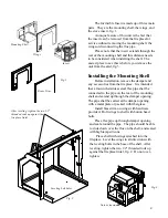
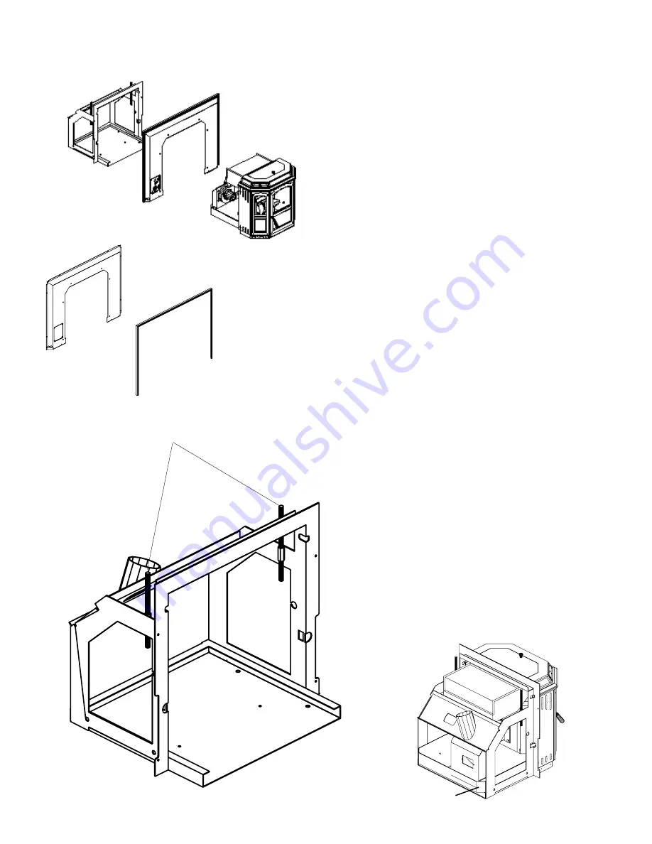
The Invincible Insert is made up of three main

parts.  They are the mounting shell, the wings, and
the stove insert, fig. 1.

A unique feature of this unit is the fact that

the insert can be removed from the fireplace for
service without removing the mounting shell, the
wings or disconnecting the flue pipe.

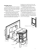
Please note that the insert extends through the

rear of the mounting shell and this distance needs
to be considered when installing the shell.  The
easiest place to see this is before you remove the
unit from the skid, fig.3.

Installing the Mounting Shell

Before installation, remove the damper and

any accessories from the fireplace.  It is intended
that a four inch stainless steel flex pipe shall be
connected to the pipe on the rear of the mounting
shell and extend up through the damper opening.
The pipe shall be sealed at the damper opening
with a metal plate or packed with fiberglass.

Install brass trim on wings with hardware

provided.  Bolt wings to shell with button head
bolts.

Place flex pipe up through damper opening

and seal around the pipe.  The pipe should be able
to slide down over the flue on the shell, and sealed
with high temp silicone.

Place shell with wings attached into the

fireplace.  Level the wings in all directions with
the leveling bolts in the base of the shell.  After
leveling, tighten the two 1/2" threaded rods up
against the fireplace lintel, fig. 2.  Do not over-
tighten.

Leveling bolt holes

Mounting Shell

Wings

Insert

After leveling, tighten the two 1/2"
threaded rods up against the
fireplace lintel.

Brass Trim

Fig. 1

Fig. 2

Fig. 3

Note extension

Содержание INVINCIBLE PELLET INSERT

Страница 1: ...1 INVINCIBLE PELLET INSERT OWNERS MANUAL R4...

Страница 2: ...nstallation Assembly 3 Operation 7 ESP Control 10 Maintenance 11 Trouble Shooting 13 Wiring Diagram 14 Feeder Parts 15 Specifications 16 Manufactured by Harman Stove Company 352 Mountain House Road Ha...

Страница 3: ...g Brush 2 1 2 x 12 Threaded Rods Inside Wing box 1 Air Intake Grill 1 Hardware Pack 6 1 4 x 20 x 1 2 Bolts 6 10 32 x 1 4 Bolts 2 10 32 Nuts 1 Set of Brass Trim for Wings Assembly and Installation Dist...

Страница 4: ...ex pipe shall be connected to the pipe on the rear of the mounting shell and extend up through the damper opening The pipe shall be sealed at the damper opening with a metal plate or packed with fiber...

Страница 5: ...and reconnected after mounting Be sure to put the green wires on the stud behind the wing This stud also has the green wire from the power cord on it fig 5 Next slide the insert to within an inch of...

Страница 6: ...andle Brass Hopper Knob Plug into a 120 volt receptacle Final Assembly Install Wooden Door Handle with 1 4 x 20 x 2 1 2 bolt Install Brass Hopper Knob with 10 32 x 1 2 bolt Install the two Firebricks...

Страница 7: ...combustion blower to high When starting a fire always turn the mode selector to OFF before selecting the desired mode This resets the control for start up Turn Temp Dial to 7 This will allow the stove...

Страница 8: ...ure In Room Temp Mode this would be the outer scale marked in degrees In Stove Temp Mode this would be the inner scale marked from 1 to 7 Apply starting gel to pellets in burn pot as shown on fig 10 a...

Страница 9: ...oom Temp Mode fuel consumption is sacrificed for exact room temperature Therefore as it gets colder more pellets will be burned automatically The distribution blower speed will vary according to the p...

Страница 10: ...ll your Harman Dealer 3 Blinks Indicates ESP Exhaust Sensing Probe failure This requires a manual reset 4 Blinks Can occur only in Room Temp Mode and indicates Room Sensing Probe failed or not install...

Отзывы: