background image

8

MOUNTING OPTIONS

MOUNTING OPTIONS

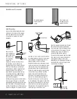
They may be wall-
mounted using the 
supplied brackets.

Satellites and Surrounds

The satellite speakers
may be placed on 
a shelf.

Wall-Mounting

Unscrew the bolt that attaches the black
shelf stand to the bottom of the speaker.
Store the stand and bolt in a safe place 
in case they are needed for a future 
installation.

Mount the wall-
bracket attachment
plate on the wall in
the desired loca-
tion. If possible,
position the 
speakers so that the mounting screws 
(not included; use size #8) may be 
installed directly into a wooden wall stud.
If that is not possible, use optional wall
anchors that are rated to support at least
twenty-five pounds.

The customer is 

responsible for proper selection and use 
of mounting hardware, available through
hardware stores, to properly and safely 
wall-mount the speakers.

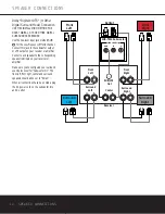
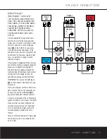
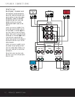
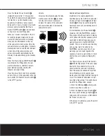
Referring to the speaker connection instruc-
tions on pages 9 through 12, thread the
appropriate speaker cable through the open-
ing in the bottom of the attachment plate,
and then through the back of the bracket as
shown in the diagram. The bracket has two

openings on top: a round screw hole, and an
arc-shaped opening in front of it. The speaker
cable should be threaded through the arc-
shaped opening, not the screw hole.

Attach the bracket to the wall plate by insert-
ing the tab at the top of the attachment plate
into the slot on top of the bracket and snap-
ping the bracket onto the attachment plate.

Thread the cable through the round opening
in the terminal cover, and then insert the
speaker wires into the terminals on the
underside of the speaker, remembering to
observe the correct polarity (see page 9).

Place the terminal cover over the opening
on the underside of the speaker so that it fits
flush against the speaker and covers the ter-
minals, with its round opening exposing the
threaded insert. The bracket fits through the
round opening in the terminal cover.

Insert the supplied bracket bolt up through
the bottom of the bracket and terminal
cover, and screw it into the threaded insert
on the underside of the speaker. The bolt
should be snug, but not so tight as to 
prevent the bracket from pivoting.

The wall-mounted speaker may be pivoted
from side to side; however, the bracket is

not

designed to tilt up or down, and

attempting to tilt it will damage the bracket
and possibly the wall, which would not be
covered by your warranty.

Remove 
Stand

15mm

or 1/2"

Wires to Speaker

Terminal Cover

Overhead

View

Wire 
From
Wall 
Plate

Wall 

23mm
or 3/4"

(M6–1.25P 
or 1/4"–20)

Wall Bracket

Wall Plate

HKTS 14 OM  11/4/03  11:32 AM  Page 10

Содержание HKTS 14

Страница 1: ...HKTS 14 HOME THEATER SPEAKER SYSTEM OWNER S MANUAL Power for the Digital Revolution...

Страница 2: ...11 Dolby Pro Logic Non Digital Line Level 12 Dolby Pro Logic Non Digital Speaker Level 13 Operation 13 Volume 13 Additional Bass Adjustments 14 Troubleshooting 15 Specifications Typographical Convent...

Страница 3: ...supporting structure grounding of the lead in wire to an antenna discharge unit size of grounding conductors location of antenna discharge unit connection to grounding electrodes and requirements for...

Страница 4: ...ardon receiver The HKTS 14 subwoofer is easy to connect to your system since it s equipped with a special subwoofer input for use with equip ment that has a dedicated subwoofer con nection that carrie...

Страница 5: ...voiding inefficiency and distortion Engage this filter when using the Speaker Level Inputs or when using the Line Level Full Range Inputs unless your receiver or processor processes its line level out...

Страница 6: ...a rate subwoofer output use a Y adaptor not supplied to bridge the receiver s preamp out put to the main amp input for that channel and connect the long end of the adaptor to the corresponding line le...

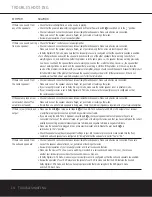
Страница 7: ...et as shown in the drawing Subwoofer The low frequency material reproduced by the subwoofer is mostly omnidirectional and this speaker may be placed in a con venient location in the room However the m...

Страница 8: ...The speaker cable should be threaded through the arc shaped opening not the screw hole Attach the bracket to the wall plate by insert ing the tab at the top of the attachment plate into the slot on to...

Страница 9: ...s on your receiver or amplifier The lead of the speaker wire is indicated with a stripe and has the colored band cor responding to the speaker s position It is important to connect all speakers identi...

Страница 10: ...onnect each speaker to the corresponding speaker terminals on your receiver or amplifier Make sure you ve configured your surround sound processor for Subwoofer On The front left front right center an...

Страница 11: ...adaptor not supplied to bridge the receiver s preamp output to the main amp input for that channel and connect the long end of the adaptor to the corre sponding line level input on the SUB TS14 IMPORT...

Страница 12: ...OUTPUT Connect your receiver or amplifier s front left and right speaker terminals to the left and right Speaker Level Input termi nals on the SUB TS14 subwoofer that are marked High Level In Connect...

Страница 13: ...to decrease the subwoofer s volume Additional Bass Adjustments In addition to the volume adjustments described above the SUB TS14 subwoofer includes a Phase Switch and a Filter Switch that can be used...

Страница 14: ...mode If your receiver processor is set in Dolby Digital or DTS mode make sure the receiver processor is configured so that the center speaker is enabled If the system plays at low Check all wires and...

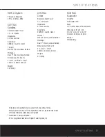
Страница 15: ...8 ohms nominal Sensitivity 86dB 1 watt 1 meter Tweeter One 3 4 dome video shielded Midrange Dual 3 drivers video shielded Dimensions H x W x D 9 9 16 x 3 15 16 x 3 5 8 243mm x 100mm x 92mm Weight 2 2...

Страница 16: ...250 Crossways Park Drive Woodbury New York 11797 516 255 HKHK 4545 Fax 516 682 3523 2003 Harman International Industries Incorporated Printed 10 03 Part No 406 000 00981...

Отзывы: