background image

20

20

INSTALLATION

connect the HK 3485’s Remote IR Output to the source device’s
Remote IR Input, which will pass any applicable remote signals trans-
mitted through the HK 3485 to the source device. This enables you 
to control your sources even when the HK 3485 itself is controlled 
via an external IR receiver.

To control more than one source device using the Remote IR Output,
connect all sources in “daisy chain” fashion, with the HK 3485’s Remote
IR Output connected to the first device’s Remote IR Input, that device’s
Remote IR Output connected to the next device’s Remote IR Input, and
so forth. See Figure 19.

Figure 19 – Remote IR Input and Output

NOTE:

Not all remote-controllable devices are equipped with

compatible IR inputs and outputs. Check with the manufacturer
of the source device for more information on the type of IR 
signal expected. The HK 3485 will output a “stripped carrier”
IR signal.

Step Seven – Connect Optional External
Equipment

If you wish to use the HK 3485 with an external power amplifier,
remove the jumpers connecting the Preamp Outputs and Main-Amp
Inputs. Store the jumpers in a safe place in case they are needed in the
future. Connect the left and right Preamp Outputs of the HK 3485 to 
the analog audio inputs on the external power amplifier. See Figure 20.

Figure 20 – Preamp Outputs and Main-Amp Inputs

You may adjust the Volume and Tone Controls using the HK 3485’s
front panel or remote.

If you wish to connect an external processor, such as an equalizer, you
may connect it to the Preamp Outputs and Main-Amp Inputs. Remove
the jumpers and store them in a safe place. Connect the HK 3485’s
Preamp Outputs to the processor’s analog audio inputs, and then con-
nect the processor’s analog audio outputs to the Main-Amp Inputs on
the HK 3485.

Alternatively, you may connect the external processor to the HK 3485’s
Tape Monitor Loop. See Figure 14.

Step Eight – Plug In AC Power

Having made all of your wiring connections, it is now time to plug each
component’s AC power cord into a working outlet.

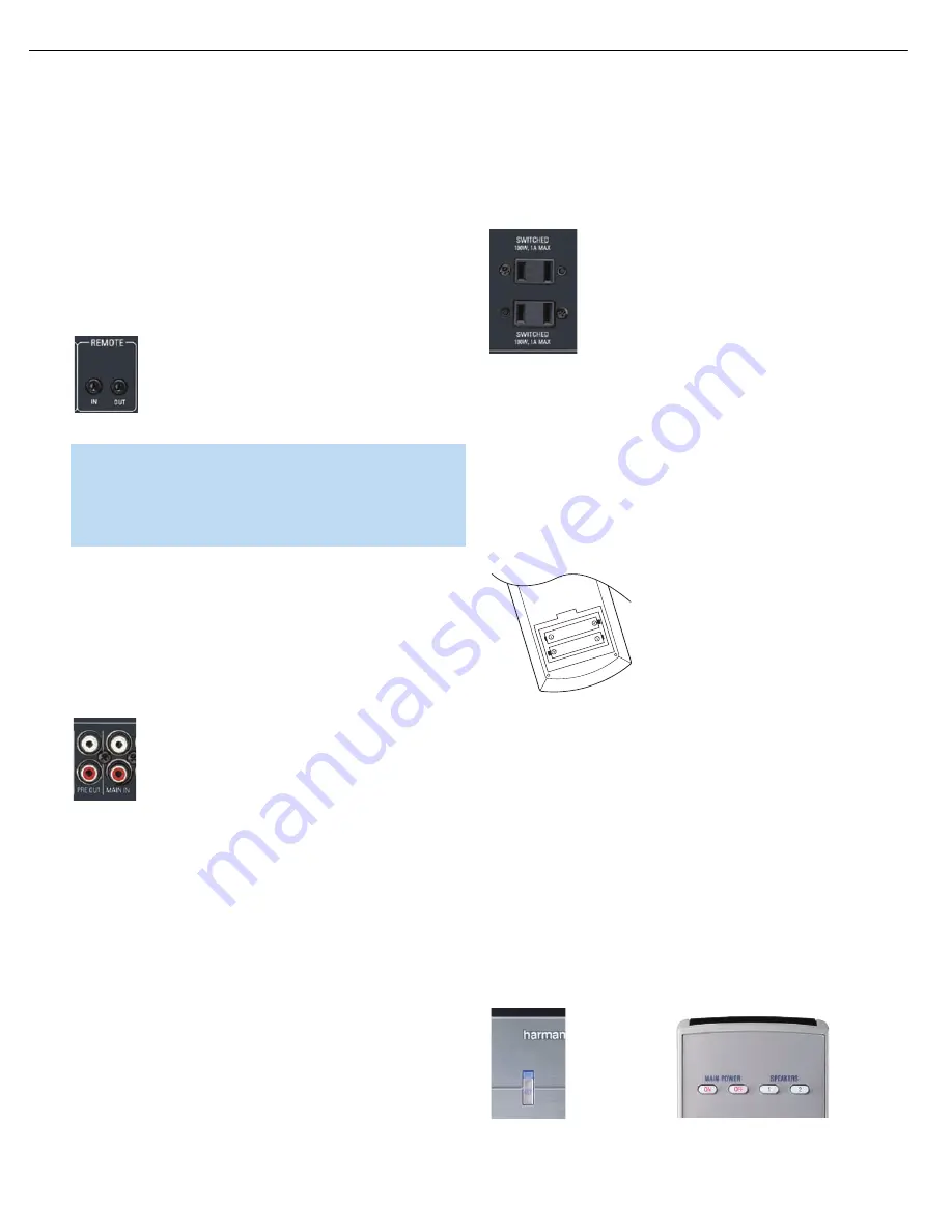
You may plug two devices into the AC Switched Accessory Outlets on
the rear of the HK 3485. See Figure 21. Make sure each device draws
no more than 100 watts. The devices should have their mechanical or
master power switches turned on, and they will power on any time the
HK 3485 is turned on.

Figure 21 – Switched AC Accessory Outlets

Step Nine – Insert Batteries in Remote

The HK 3485 remote control uses two AAA batteries, which are included.

To remove the battery cover located on the back of the remote, firmly
press the ridged depression and slide the cover toward the bottom of 
the remote.

Insert the batteries as shown in the diagram, making sure to observe 
the correct polarity. See Figure 22.

Figure 22 – Remote Battery Compartment

When using the remote, remember to point the lens toward the front
panel of the HK 3485. Make sure no objects, such as furniture, are
blocking the remote’s path to the receiver. Bright lights, fluorescent lights
and plasma video displays may interfere with the remote’s functioning.
The remote has a range of about 20 feet, depending on the lighting
conditions. It may be used at an angle of up to 30 degrees to either
side of the HK 3485.

If the remote seems to operate intermittently, then make sure the batteries
have been inserted correctly, or replace the batteries with fresh ones.

Step Ten – Turn On the HK 3485

T

he HK 3485 may be turned on from Standby mode by pressing the

Power Switch on either the front panel or the remote. See Figures 23
and 24.

Figure 23 – Front-Panel Power Switch        Figure 24 – Remote Control Power Switch

HK 3485 OM  2/15/07  4:20 PM  Page 20

18

HK3485            

harman/kardon


Содержание HK 3485

Страница 1: ...ONS 11 CONNECTIONS INSTALLATION 13 OPERATION 19 TROUBLESHOOTING GUIDE 23 PROCESSOR RESET 23 DISASSEMBLY PROCEDURES 24 EXPLODED VIEW 25 AMPLIFIER BIAS ADJUSTMENT 26 BLOCK DIAGRAM 27 IC DESCRIPTIONS PIN...

Страница 2: ...or to applying power to the unit under test 2 After removing an electrical assembly equipped with ES devices place the assembly on a conductive surface such as aluminum foil to prevent electrostatic c...

Страница 3: ...l overlays control shaft etc Plug the AC line cord of the appliance directly into a 120V AC 60Hz outlet and turn the AC power switch on Any current measured must not exceed o 5mA ANY MEASUREMENTS NOT...

Страница 4: ...rtion 1kHz 50 Mod 0 8 Selectivity 10kHz 25dB Video Section Television Format NTSC PAL SECAM Signal Format Composite Input Level 1Vp p Input Impedance 75 Ohms unbalanced Sync Polarity Negative Output L...

Страница 5: ...5...

Страница 6: ...and Video Inputs Connect a source component that will only be used temporarily to these jacks such as a camera or game console or connect an iPod using the supplied audio video cable Balance Control T...

Страница 7: ...Control CD Source Selector Tape Source Selector Phono Source Selector Video Source Selectors Message Display Dimmer Sleep Treble Control Balance Control NOTE To make it easier to follow the instructi...

Страница 8: ...se The numbers in the Preset Number Sleep Timer Indicators will show the minutes remaining before the HK 3485 turns off Preset Indicator This indicator lights when the tuner is in use to show that the...

Страница 9: ...o conductor speaker wire to connect each set of terminals to the correct speaker Remember to observe the correct polarity positive and negative connections Always connect the positive lead to the red...

Страница 10: ...Subwoofer Outputs Main Amp Inputs Speaker 2 Outputs Switched AC Accessory Outlets Speaker 1 Outputs Phono Inputs and Ground CD Inputs Tape Inputs Tape Outputs NOTE To make it easier to follow the inst...

Страница 11: ...ndicator in the Message Display lights steadily rear panel connections selected or flashes front panel connections selected Preset Stations Selectors Track Skip Press these buttons to select a preset...

Страница 12: ...e button press To start the process make sure the FM tuner has been selected as the source Press and hold this button The Memory and Preset Indicators will flash as the HK 3485 tuner scans through all...

Страница 13: ...collar is revealed 2 Insert the bare end of the wire into the hole 3 Screw the cap back into place until the wire is held snugly Figure 2 Binding Post Speaker Terminals With Bare Wires Subwoofer The s...

Страница 14: ...analog audio jack although it is important never to confuse the two Do not plug a com posite video cable into an analog audio jack and vice versa Both the chrominance color and luminance intensity com...

Страница 15: ...irs of speakers simultaneously See Figure 9 Figure 9 Speaker Connections Step Two Connect the Subwoofer Connect the Subwoofer Outputs on the HK 3485 to the line level inputs on your subwoofer The same...

Страница 16: ...e other available audio input sources on the HK 3485 Compact Disc CD Player Connect the analog audio outputs of your CD player or another audio only device to the CD Audio Inputs See Figure 13 Figure...

Страница 17: ...el or remote repeatedly When the dot to the left of the Video 3 Input Indicator on the front panel of the HK 3485 is lit steadily the rear panel inputs are active When the dot flashes the front panel...

Страница 18: ...rocessor s analog audio outputs to the Main Amp Inputs on the HK 3485 Alternatively you may connect the external processor to the HK 3485 s Tape Monitor Loop See Figure 14 Step Eight Plug In AC Power...

Страница 19: ...mer and the SLEEP OFF message will appear Volume Control The volume may be adjusted either by turning the knob on the front panel clockwise to increase volume or counterclockwise to decrease volume or...

Страница 20: ...to the HK 3485 remember to select two channel audio in the DVD player and disc menus The HK 3485 does not switch the last selected video source when an audio only source such as Phono CD or Tape CDR i...

Страница 21: ...u may automatically program all FM radio stations in your area that are received with acceptable signal strength into the HK 3485 s presets Press and hold the Auto Preset Button until the Memory and P...

Страница 22: ...the AC power cord for at least three minutes Plug the cord back in and turn the receiver back on If this doesn t help you may want to try a system reset NOTE A system reset erases all user configurat...

Страница 23: ...ith a phono preamp Turntable not plugged into Phono Inputs Do not use a turntable with any inputs other than the Phono Inputs unless it has a moving magnet type cartridge and includes a phono preamp N...

Страница 24: ...24 HK3485 harman kardon...

Страница 25: ...25...

Страница 26: ...26 HK3485 harman kardon...

Страница 27: ...RY 27...

Страница 28: ...16K 60K Bytes VDD RESET PORT F PF7 0 8 bits TIMER A BEEP PORT A RAM 512 2048 Bytes PORT C 10 BIT ADC VAREF VSSA PORT B PB7 0 8 bits PWM ART PORT E PE7 0 8 bits SCI TIMER B PA7 0 8 bits PORT D PD7 0 8...

Страница 29: ...5 26 27 28 1 2 3 4 5 6 7 8 9 10 11 12 13 14 15 16 ei2 ei3 ei0 ei1 PWM3 PB0 PWM2 PB1 PWM1 PB2 PWM0 PB3 ARTCLK HS PB4 ARTIC1 PB5 ARTIC2 PB6 PB7 AIN0 PD0 AIN1 PD1 AIN2 PD2 AIN3 PD3 HS PE4 HS PE5 HS PE6 H...

Страница 30: ...4 2 PE5 HS I O CT HS X X X X Port E5 3 PE6 HS I O CT HS X X X X Port E6 4 PE7 HS I O CT HS X X X X Port E7 5 PB0 PWM3 I O CT X ei2 X X Port B0 PWM Output 3 6 PB1 PWM2 I O CT X ei2 X X Port B1 PWM Outp...

Страница 31: ...B Output Compare 1 ADC Analog Input 13 37 PC2 HS ICAP2_B I O CT HS X X X X Port C2 Timer B Input Capture 2 38 PC3 HS ICAP1_B I O CT HS X X X X Port C3 Timer B Input Capture 1 39 PC4 MISO ICCDATA I O...

Страница 32: ...tage 58 OSC23 I O Resonator oscillator inverter output or ca pacitor input for RC oscillator 59 OSC13 I External clock input or Resonator oscillator inverter input or resistor input for RC oscilla tor...

Страница 33: ...33 HK3485 harman kardon...

Страница 34: ...34 HK3485 harman kardon...

Страница 35: ...p 6 2dB Amp S4 S3 S6 S7 20K 20K 20K 13 Vin1 V V SW2 SW1 Vout1 Vout2 Vout3 SW4 BLOCK DIAGAM NJM2296M IC91 SW3 GND SW5 Vin2 Vin3 Vin4 Vin5 1 15 11 16 10 14 12 2 9 7 5 4 6 8 3 20K 20K 20K 20K 20K 75 dirv...

Страница 36: ...36 HK3485 harman kardon...

Страница 37: ...37 HK3485 harman kardon...

Страница 38: ...S R COM R S R S R COM R S R S R COM DATA CK LEVEL SHIFTER 2 1 2 3 1 4 5 6 2 7 8 3 1 2 3 1 4 5 6 2 7 8 3 1 3 4 5 6 7 8 9 10 14 28 11 12 13 27 26 25 24 23 22 21 20 19 18 17 16 15 LATCH CIRCUIT SHIFT RE...

Страница 39: ...39 HK3485 harman kardon...

Страница 40: ...40 HK3485 harman kardon...

Страница 41: ...41 HK3485 harman kardon...

Страница 42: ...CEA1CKS4R7T CAP ELECT 4 7UF 16V C822 HCBS1H151KBT CAP CERAMIC 150PF 50V K C832 833 HCBS1H102KBT CAP CERAMIC 1000PF 50V B C835 CCEA0JH102T CAP ELECT 1000PF 6 3V C904 908 CCKT1H101KB CAP CERAMIC 100PF 5...

Страница 43: ...RBON 1 8K OHM 1 5W J R858 868 CRD20TJ562T RES CARBON 5 6K OHM 1 5W J R859 869 CRD20TJ752T RES CARBON 7 5K OHM 1 5W J R875 CRD20TJ820T RES CARBON 82 OHM 1 5W J R878 CRD20TJ273T RES CARBON 27K OHM 1 5W...

Страница 44: ...C313 314 HCBS1H330JT CAP CERAMIC 33PF 50V C315 316 317 CCEA1HH100TS CAP ELECT 10UF 50V 105 C C318 CCEA1HH100T CAP ELECT 10UF 50V C319 320 607 609 HCQI1H473JZT CAP MYLAR 0 047UF 50V J C343 CCEA1AH471T...

Страница 45: ...RES CARBON 470 OHM 1 5W J R122 CRD25TJ101T RES CARBON 100 OHM 1 4W J R151 164 CRD20TJ474T RES CARBON 470K OHM 1 5W J R191 194 205 208 CRD20TJ184T RES CARBON 180K OHM 1 5W J R212 CRD25TJ471T RES CARBON...

Страница 46: ...6200BM WIRE ASS Y JW31 CWE7202050AA WIRE ASS Y JW32 CWE7202070AA WIRE ASS Y JW33 CWE7202060AA WIRE ASS Y JW34 35 CWE7202090AA WIRE ASS Y CN26 CJP13GA115ZY WAFER CARD CABLE CN31 32 CJP02GA01ZY WAFER CN...

Страница 47: ...47 HK3485 harman kardon...

Страница 48: ...48 HK3485 harman kardon...

Страница 49: ...49 HK3485 harman kardon...

Страница 50: ...50 HK3485 harman kardon...

Страница 51: ...51 HK3485 harman kardon...

Отзывы: