


SYSTEM CONFIGURATION
25
System Configuration
configuration button has been pressed the test
noise will be heard from the front left speaker.
6. At this point, EzSet will take over, adjusting
the output level of each channel so that when
the process is complete all levels will be equal
and at the set reference point. This process
may take a few minutes, depending on the
extent of adjustment required.
7. During the adjustment, you will see the loca-
tion of the channel position being adjusted
appear in the on-screen display (if connected)
and in the
Main Information Display
˜
,
alternating with a readout of the output set-
ting, relative to the reference volume level.
As the adjustment proceeds, a few things will
happen simultaneously:
• The channel position being adjusted will flash
in the
Speaker/Channel Input Indicators
$
. If the test noise is heard from a channel
other than the one shown in the Indicator, the
on-screen display or the front panel display,
there is an error in the speaker connections.
If this is the case, press the
Test Button
8
TWICE to stop the adjustment. Then, turn the
unit off and verify that all speakers are con-
nected to the proper
Outputs
(
.
Afterwards start the adjusting process again
from the beginning.
• As the individual channels are set, the channel
name and the adjustment offset will appear in
the on-screen display (if connected) and the
Main Information Display
˜
. While the
level is changing, the
Program/SPL Indicator
2
will change colors to reflect the output
level in relation to the reference.
A red indication shows that the level is too
high, while an orange indication shows that
the level is too low. When the indicator is
green, the level is correct, and the test noise
will move to the next channel.
• While adjustments are being made, the red
LED under the
AVR Selector
f
will flash.
This is normal, and indicates that EzSet is oper-
ating.
8. After the test noise has circulated once
through each channel, it will send the tone to
each channel once again, to verify the settings.
9. After two complete circulations of the tone,
the levels are set. The
Program/SPL
Indicator
2
will remain green at each
channel. Upon completion of the second circu-
lation, the
Program/SPL Indicator
2
will
flash green twice and then go out. The tone
will stop and the AVR will return to normal
operation.
If you find that the output levels chosen by EzSet
are either much lower or much higher than the
"0dB" reference setting or even at the limits of
the +/-10dB variation range for the output levels,
depending on the sensitivity of the speakers in
use and your specific room layout, you may
repeat the procedure. Return to Step 2 and
adjust the master volume either higher or lower
appropriately to the output levels set previously
(e.g. when levels were set to about "–7dB"
reduce the master volume for 7dB), to accommo-
date your particular room layout and your speak-
ers. You may repeat this procedure as many times
as necessary to achieve a desired result. In order
to prevent possible damage to your hearing or
your equipment, we emphasize that you should
avoid setting the master volume above 0dB.
NOTE:
The subwoofer output is not adjusted
when the test tone is in use. To adjust the
subwoofer output you must use an external
source, following the instructions on page 33.
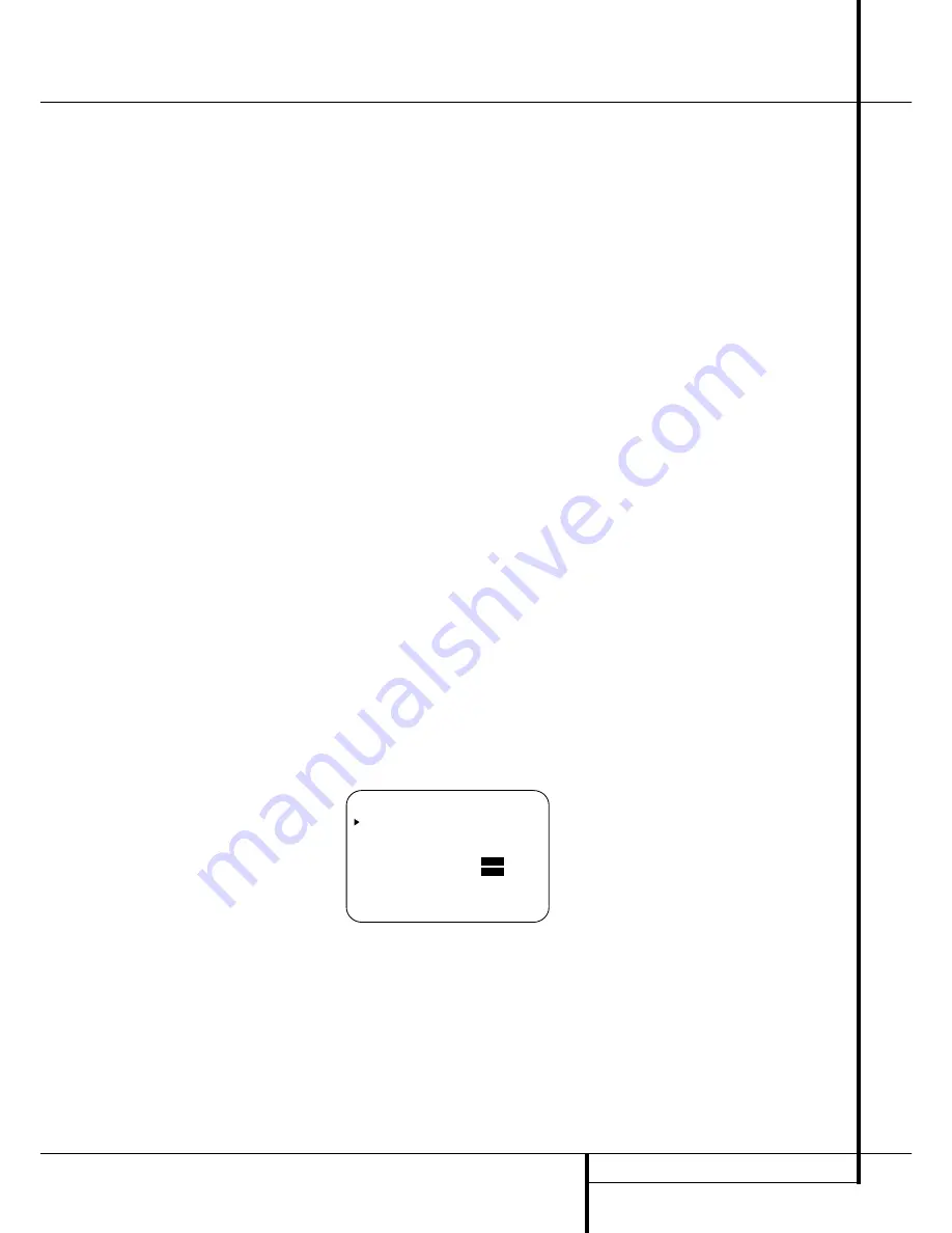
Manual Output Level Adjustment
Output levels may also be adjusted manually,
either to set them to a specific level with an SPL
meter, or to make fine tuning adjustments to the
levels obtained using the EzSet remote.
Manual output level adjustment is most easily
done through the
CHANNEL ADJUST
menu (Figure 8). If you are already at the main
menu, press the
¤
Button
D
until the on-
screen
›
cursor is next to the
CHANNEL
ADJUST
line. If you are not at the main menu,
press the
OSD Button
v
to bring up the
MASTER M E N U
(Figure 1), and then press
the
¤
Button
D
four times so that the
onscreen
›
cursor is next to the
CHANNEL
ADJUST
line. Press the
Set Button
F
to
bring the
CHANNEL ADJUST
menu
(Figure 8) to the screen.
Figure 8
Once the menu appears on your video screen,
first use the
⁄
Button
D
to move the on-
screen
›
cursor so that it is next to the
TEST
TONE
line. Press the
‹
/
›
Buttons
E&
so that
ON
is highlighted.
You will hear a test noise circulate from speaker
to speaker in a clockwise direction around the
room. The test noise will play for two seconds in
each speaker before circulating, and a blinking
on-screen cursor will appear next to the name of
each speaker location when the sound is at that
speaker. Now turn up the volume until you can
hear the noise clearly.
IMPORTANT NOTE:
Because this test noise will
have a much lower level than normal music, the
volume must be lowered after the adjustment for
all channels is made, but BEFORE you return to
the main menu and the test tone turns off.
NOTE:
Remember to verify that the speakers
have been properly connected. As the test noise
circulates, listen to make certain that the sound
comes from the speaker position shown in the
Main Information Display
˜
. If the sound
comes from a speaker location that does NOT
match the position indicated in the display, turn
the AVR off using the
Main Power Switch
1
and check the speaker wiring or connections to
external power amplifiers to make certain that
each speaker is connected to the correct output
terminal.
After checking for speaker placement, let the test
noise circulate again, and listen to see which
channels sound louder than the others. Using the
front left speaker as a reference, press the
‹
/
›
Buttons
E&
on the remote to bring all
speakers to the same volume level. When one of
the
‹
/
›
buttons is pushed, the test noise circula-
tion will pause on the channel being adjusted to
give you time to make the adjustment. When you
release the button, the circulation will resume
after five seconds. The on-screen cursor
›
and the
test noise can also be moved directly to the
speaker to be adjusted by pressing the
⁄
/
¤
buttons
D
on the remote.
Continue to adjust the individual channels until
the volume level sounds the same from each
speaker. Note that adjustments should be made
with the
‹
/
›
Buttons
E&
on the remote
only, NOT the main volume controls.
If you are using a sound-pressure level (SPL)
meter for precise level adjustment with the test
tone, open the main
Volume Control
)
to
–15dB and set the individual output level for
each channel so that the meter reads 75dB,
C-Weighted Slow. After all settings are made turn
the main volume down.
* C H A N N E L A D J U S T *
F L : 0 d B S B R : 0 d B
C E N : 0 d B S B L : 0 d B
F R : 0 d B S L : 0 d B
S R : 0 d B S U B : 0 d B
C H A N N E L R E S E T :
O F F
O N
T E S T T O N E :
O F F
O N
B A C K T O M A S T E R M E N U


