background image

SYSTEM CONFIGURATION

25

System Configuration

input signal to both front speakers, to the rear
speakers and to both surround back speakers (if
in use), while the monophonic signal parts are
spread over all speakers, also the Center.
See page 29 for a complete explanation of the 
5 Stereo and 7 Stereo modes.

After the selections are made in the Dolby, DTS,
Logic 7, DSP (Surround) or Stereo menus, press
the 

/

¤

buttons 

D

so that the cursor moves

to the 

BACK TO

SURR SELECT

line and

presss the 

Set Button 

F

.

Adjustments for Other Inputs

After one input has been adjusted for analog or
digital input, speaker type and surround mode,
return to the 

INPUT SETUP

line on the

MASTER

menu and enter the settings for each

input that you will use. In most cases, only the
digital input and surround mode may be different
from one input to the next, while the speaker type
will usually be the same (inputs set to

GLOBAL

). But if prefered you can also select

different speaker types or turn speakers on or off
individually for each input in use.

Delay Settings 

Due the different distances between the listening
position for the front channel speakers and the
surround speakers, the amount of time it takes for
sound to reach your ears from the front or sur-
round speakers is different. You may compensate
for this difference through the use of the delay
settings to adjust the timing for the specific
speaker placement and acoustic conditions in
your listening room or home theater.

To re-synchronize the front, center and surround
channels at first measure and note the distance
from the listening/viewing position to the front,
center, surround and surround back (if any)
speakers in meters.

The Delay setting for all speakers configured for
your system will be available only (with 5.1 or
with 6.1/7.1 configuration) when any Dolby sur-
round mode is selected (except Dolby-3-Stereo).
In addition they are selectable with these modes
only, with all other modes the delay times are
fixed.
Note that the Delay settings are "Global" for all
inputs, using those Dolby modes, and need not to
be repeated with any input.

To start with the delay settings at first select any
input associated with such a Dolby mode. Next,
continue within the 

M A S T E R M E N U

(Figure 1). If the system is not already at that
point, press the 

OSD

button 

L

to bring up the

master menu. Press the 

¤

Button

D

three

times or until the on-screen 

cursor is pointing

at the 

DELAY ADJUST

line. Press the 

Set

Button

F

to call up the menu.
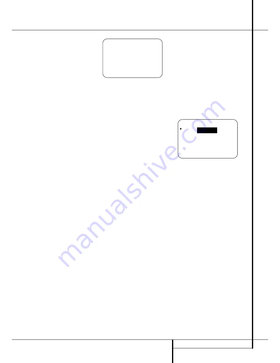
Figure 7

Next move the 

cursor to the 

UNIT

line and

select the unit for distances you prefer to enter,
feet or meter. Then move the 

cursor to the

CENTER

line where the first adjustment is

made. Now press the 

/

Buttons

E&

until

the distance from the center speaker to the pre-
ferred listening position is entered. When the

C E N T E R D E L A Y

is entered, press the 

¤

Button

D

once to move to the next line.

Now the 

cursor will be at the 

SURROUND

line so that the delay for the surround speakers
may be set. Press the 

/

Buttons

E&

until

the distance from the video display at the front of
the room to the surround speakers is entered.
Finally, if the system is  configured for 7.1 opera-
tion by entering 

LARGE

or 

SMALL

on the

SURR BACK

line of the 

SPEAKER

SETUP

menu, press the 

¤

Button

D

again

and use the 

/

Buttons

E&

to enter the

distance from the video display at the front of the
room to the surround speakers. Remember that
this last adjustment will only be needed when you
have surround back speakers installed and Dolby
Digital chosen as the surround mode.

When the delay settings are complete, press the

¤

Button

n

once so that the cursor is next to

the 

BACK TO MASTER MENU

line and

press the 

Set Button 

p

to return to the

MASTER

menu.

Note that the delay settings may also be adjusted
at any time when the Dolby Digital or Dolby Pro
Logic II modes are in use by pressing the 

Delay

button on the remote 

%

. Then press the 

/

¤

D

buttons on the remote to select the Center

or Rear channels for adjustment, followed by a
press of the 

Set

button 

F

. Next, press the

/

¤

buttons 

D

on the remote until the

desired figure appears in the 

Main Information

Display

˜

and press the 

Set button

p

twice to confirm the setting and return to the nor-
mal display.

Night Mode Settings

The Night mode is a feature of Dolby Digital that
uses special processing to preserve the dynamic
range and full intelligibility of a movie sound track
while reducing the peak level. This prevents
abruptly loud transitions from disturbing others,
without reducing the sonic impact of a digital
source. Note that the Night mode is only available
when the Dolby Digital surround mode is selected.

To adjust the Night mode setting from the menu
press the 

OSD

Button 

L

so that the 

MASTER

menu appears. Then press the 

¤

button 

D

once and press 

Set

F

to select the

SURROUND SETUP

menu. Again press the 

¤

button 

D

once and press 

Set

F

to select

the 

DOLBY

menu (see fig. 6).

Figure 6

To adjust the Night mode setting, make certain
that the 

cursor is on the 

NIGHT

line of the

DOLBY

menu. Next, press 

/

Buttons

E&

to choose between the following settings.

OFF

: When 

OFF

is highlighted, the Night mode

will not function.

MID

: When 

MID

is in the highlighted video, a

mild compression will be applied.

M

A X

: When 

MAX

is in the highlighted video, a

more severe compression algorithm will be applied.

When you want to use the Night mode feature,
we recommend that you select the MID setting as
a starting point and change to the MAX setting
later, if desired.

When the setting has been made, press the 

/

¤

buttons 

D

so that the 

cursor is next to

BACK T O SURR SELECT

, and press the

Set

button 

F

to return to the 

SURROUND

SELECT

menu.

Note that the Night mode may be adjusted direct-
ly any time that Dolby Digital surround mode is
selected by pressing the 

Night

button 

B

. When

the button is pressed, the words 

D-RANGE

followed by the current setting (

MID

,

MAX

,

OFF

) will appear in the lower third of the video

screen and in the 

Main Information Display

˜

. Press the 

/

¤

buttons 

D

within five sec-

onds to select the desired setting, then press 

Set

F

to confirm the setting.

        * *   D O L B Y   * *

M O D E :  

D O L B Y  


D I G I T A L

N I G H T :   O F F   M I D   M A X

B A C K   T O   S U R R   S E L E C T

* *   D E L A Y   A D J U S T   * *

C E N T E R               : 1 0 F T

S U R R O U N D           : 1 0 F T

S U R R   B A C K         : 1 0 F T

U N I T :     F E E T       M E T E R

B A C K   T O   M A S T E R   M E N U

Содержание AVR 4550

Страница 1: ...AVR 4550 Audio VideoReceiver OWNER S MANUAL AVR 4550 ready LOGIC7 VMAx Power for the Digital Revolution ...

Страница 2: ...Tuning 40 RDS Operation 40 RDS Tuning 40 RDS Display Options 40 Program Search 41 Programming the Remote 41 Programming the Remote with Codes 41 Direct Code Entry 41 Auto Search Method 42 Code Readout 42 Learning Codes 42 Erasing Learned Codes 43 Macro Programming Table of Contents Typographical Conventions In order to help you use this manual with the remote control front panel controls and rear ...

Страница 3: ...R 4550 features connections for five video devices all with both composite and S Video inputs Two additional audio inputs are available and a total of six digital inputs and three outputs make the AVR 4550 capable of handling all the latest digital audio sources For compatibility with the latest HDTV video sources and progressive scan DVD players the AVR 4550 also features wide bandwidth low cross...

Страница 4: ...t proper space is provided both above and below the unit for ventilation If this product will be installed in a cabinet or other enclosed area make certain that there is sufficient air movement within the cabinet Under some circumstances a fan may be required Do not place the unit directly on a carpeted surface Avoid installation in extremely hot or cold locations or an area that is exposed to dir...

Страница 5: ...display and in the Lower Display Line B press the Surround Mode Selector 9 to cycle through the individual modes available For example press this button to select Dolby modes and then press the Surround Mode Selector 9 to choose from the various mode options 6 Speaker Selector Press this button to begin the process of configuring the AVR 4550 for the type of speakers it is being used with For comp...

Страница 6: ... See page 25 for more information on delay adjustments Digital Optical 3 Input Connect the optical digital audio output of an audio or video product to this jack When the Input is not in use be certain to keep the plastic cap installed to avoid dust contamination that might degrade future performance Surround Mode Indicators A green LED will light in front of the surround mode that is currently in...

Страница 7: ...nels no speaker has been selected for that position See page 21 for more information on configuring speakers The letters inside each of the center boxes display active input channels For standard analog inputs only the L and R will light indicating a stereo input When a digital source is playing the indica tors will light to display the channels begin received at the digital input When the letters...

Страница 8: ...a supplied with the receiver to these terminals If an externalAM antenna is used make connections to the AM and GND terminals in accordance with the instructions supplied with the antenna FM Antenna Connect the supplied indoor or an optional external FM antenna to this terminal Tape Inputs Connect these jacks to the PLAY OUT jacks of an audio recorder Tape Outputs Connect these jacks to the RECORD...

Страница 9: ... video outputs of a DVD player to these jacks Note All component inputs outputs can be used for RGB signals too in the same way as described for the Y Pr Pb signals then connected to the jacks with the corresponding color RGB connection is not possible if the source out puts a separate sync signal see page 16 Remote IR Output This connection permits the IR sensor in the receiver to serve other rem...

Страница 10: ... to be controlled by an external computer or programmable remote system that uses RS 232 commands Due to the complexity of RS 232 connections we recommend that they be made by a trained and qualified custom installer See page 18 for more information on the RS 232 control port Fan Vents These ventilation holes are the output of the AVR 4550 s airflow system To ensure proper operation of the unit an...

Страница 11: ...er Mode Direct Button Tuning Up Down OSD Button Dolby Mode Select Button DTS Digital Mode Selector Logic 7 Mode Select Button Transport Controls EzSet Sensor Microphone Skip Up Down Buttons Stereo Mode Select Button DTS Neo 6 Mode Select Macro Buttons RDS Selector Button Preset Up Down Clear Button Memory Button Delay Prev Ch Button Speaker Select Multiroom Volume Up Down SPL Indicator Select Lear...

Страница 12: ...Each press of the button changes the time until turn off in the following order Hold the button pressed for two seconds to turn off the Sleep mode setting Note that this button is also used to change channels on your TV VCR and Sat receiver when the appropriate source is selected using the device Input Selectors 4 A Surround Mode Selector Press this but ton to select any of the HALL THEATER or VMA...

Страница 13: ...d each subsequent press selects the next mode in the following order Macro Buttons Press these buttons to store or recall a Macro which is a pre pro grammed sequence of commands stored in the remote See page 43 for more information on storing and recalling macros RDS Select Button Press this button to dis play the various messages that are part of the RDS data system of the AVR 4550 s tuner See pa...

Страница 14: ...ressing one of these buttons will change the input Tuning Up Down Fast Play These but tons may be used to change the frequency of the tuner These buttons may also control the Fast Play or Fast Reverse functions of compatible Harman Kardon CD DVD or cassette decks in the same room or from a remote room when an IR link is connected to the AVR 4550 ƒ Record Pause Press this button to acti vate the Re...

Страница 15: ...lding codes in your area When connecting wires to the speakers be certain to observe proper polarity Note that the positive terminal of each speaker connection now carries a specific color code as noted on page 8 However most speakers will still use a red terminal for the postive connection Connect the negative or black wire to the same terminal on both the receiver and the speaker NOTE While most...

Страница 16: ...di ble visible when the VCR is playing connect the Out plugs to the In jacks on the AVR and turned around If the adapter plugs are not labeled in that way pay attention to the signal flow directions as shown in the diagrams above and in the instruction attached to the adapter If uncertain don t hesitate to consult your dealer Important Notes for S Video connections 1 Only the S Video In Out of S V...

Страница 17: ... cable specific control signals apart from Audio Video signals will be fed to the TV These specific signals are With all video sources the signal for automatic input selection that switches the TV automatically to the appropriate input as soon as the video source is started And with DVD players the signals automatically turning the TV to 4 3 16 9 format with 16 9 TVs or with 4 3 TVs with selectabl...

Страница 18: ... a setting in the Advanced Select menu following the instructions shown on page 36 NOTE For all options you may connect an optional IR sensor Harman Kardon He1000 in the remote room to the AVR 4550 via an appro priate cable Connect the sensor s cable to the Multiroom IR Input on the AVR 4550 and use the Zone II remote to control the room vol ume Alternatively you may install an optional volume con...

Страница 19: ...t of the room sound smooth When the AVR 4550 is used in 5 1 channel oper ation the preferred location for surround speak ers is on the side walls of the room at or slightly behind the listening position In a 7 1 channel system both side surround and back surround speakers are required The center of the speaker should face you see below Rear surround speakers are required when a full 7 1 channel sy...

Страница 20: ...een The Semi OSD mode uses one line displays only Note that when the full OSD system is in use the menu selections are not shown in the Infor mation Display When the full OSD menu system is used OSD ON will appear in the Upper Display Line A and the OSD Indicator C will illuminate to remind you that a video display must be used When the semi OSD system is used in conjunc tion with the discrete con...

Страница 21: ...eakers owner s manual or ask your dealer This menu screen also allows you to enter the set tings for the AVR 4550 s Triple Crossover feature that allows a different crossover point to be used for the front left right center and surround speakers In systems where full range or tower speakers are used for the front soundstage or where different brands or models are in use at the various speaker posi...

Страница 22: ...make the LARGE option available for the center speaker This is due to the requirements of Logic 7 processing and does not indicate a prob lem with your receiver When NONE is selected no signals will be sent to the center channel output The receiver will operate in a phantom center channel mode Center channel information will be sent to the left and right front channel outputs and the center channe...

Страница 23: ...st choice that is ABOVE the speaker s lowfrequency limit to avoid the creation of a low frequency hole where your system will have no bass infor mation In cases where LARGE has been selected as the front channel speaker option and LFE L R has been selected as the subwoofer option the front channel sound information below the cross over point selected for the L R front speakers when fronts are set ...

Страница 24: ...lation and Dolby 3 Stereo A com plete explanation of these modes is found on Page 28 Note that when the Dolby Digital mode is selected there are additional settings available for the Night mode that are associated with the surround mode only not with the input That s why these settings must be made only once not with each input in use They are described later in the next main chapter see below Fig...

Страница 25: ...e room to the surround speakers is entered Finally if the system is configured for 7 1 opera tion by entering LARGE or SMALL on the SURR BACK line of the SPEAKER SETUP menu press the Button D again and use the Buttons E to enter the distance from the video display at the front of the room to the surround speakers Remember that this last adjustment will only be needed when you have surround back sp...

Страница 26: ...d the test noise will be heard from the front left speaker 6 At this point EzSet will take over adjusting the output level of each channel so that when the process is complete all levels will be equal and at the set reference point This process may take a few minutes depending on the extent of adjustment required 7 During the adjustment you will see the loca tion of the channel position being adju...

Страница 27: ...channels have an equal volume level the adjustment is complete Now turn the Volume down to about 40dB otherwise the listening level may be too high as soon as the source s music starts to play To exit this menu press the buttons D until the on screen cursor is next to the BACK T O MASTER MENU line and then press the Set Button F to return to the MASTER MENU The output levels may also be adjusted a...

Страница 28: ...o Logic II Movie mode is optimized for movie soundtracks that are recorded with matrix surround by creating separate center rear left and rear right signals while the Pro Logic II Music mode should be used with musical selections that are recorded with matrix surround or even with normal stereo mode creating separate rear left and rear right signals in any case The Pro Logic II Emulation mode crea...

Страница 29: ...center and surround positions The VMAx N or Near Field mode should be selected when your listening position is less than 1 5 m from the speakers The VMAx F or Far Field mode may be selected when your listening position is greater than 1 5 m from the speakers The VMAx modes are also available using the Headphones Output 4 When headphones are being used the Far Field mode will push the sound field a...

Страница 30: ...ce Selector button Each press of the button will move the input selection through the list of available inputs As the input is changed the AVR 4550 will automatically switch to the digital input if selected surround mode and speaker configura tion that were entered during the configuration process for that source The front panel Video 4 Inputs Ô Optical Digital 3 Input or the Coaxial Digital 3 Inp...

Страница 31: ... the Dolby Pro Logic II Music or Emulation mode or Harman Kardon s exclusive Logic 7 Music mode for a dramatic improvement in comparison to the Dolby Pro Logic I mode of former times NOTE Once a program has been encoded with matrix surround information it retains the sur round information as long as the program is broadcast in stereo Thus movies with surround sound may be decoded via any of the an...

Страница 32: ...M Pulse Code Modulation is the non com pressed digital audio system used for compact discs Non Dolby Digital DTS Laserdiscs and some special PCM encoded DVDs The digital circuits in the AVR 4550 are capable of high quality digital to analog decoding and they may be connected directly to the digital audio output of your CD DVD or LD player LD only for PCM or DTS programs for Dolby Digital laser dis...

Страница 33: ...ll those tracks except 2 0 audio only the Dolby Digital and VMAx modes are available When the Dolby Digital sig nal is only two channel 2 0 these two chan nels l and r often contain Pro Logic surround informations With those tracks the AVR 4550 automatically switches to the Dolby Pro Logic II Movie mode in addition to the Dolby Digital mode but you may also select the Vmax mode When the D D 2 0 si...

Страница 34: ...source is playing it is possible to make an analog recording using the Tape or Video 1 or Video 2 or record outputs even if the source is connected to any digital input of the AVR 4550 only as long as Surround Off mode is selected possible with a PCM source only But the analog two channel signal even of a Dolby Digital not DTS source the Downmix to Stereo or Dolby Surround can be recorded by conne...

Страница 35: ...e or an external signal generator as the source the goal is to have the output level at each channel be equal when heard at the listening position with any surround mode selected When your test source is a nor mal disc with music signals you may adjust the level for each channel and surround mode as you prefer e g you may lower the center channel level when you find it to be too high or increase t...

Страница 36: ...r Indicator 3 will always remain lit to remind you that the unit is turned on If you wish to make other adjustments in the menu press the Buttons D until the on screen cursor is next to the desired setting or the BACK TO MASTER MENU line and press the Set button F If you have no other adjustments to make press the OSD Button L to exit the menu system The display brightness may also be changed by p...

Страница 37: ...D until the on screen cursor is next to the ADVANCED line Press the Set Button F to enter the ADVANCED SELECT menu Figure 11 At the ADVANCED SELECT menu make certain that the on screen cursor is next to the FULL OSD TIME OUT line by pressing the Buttons D as needed Next press the buttons E until the desired time is displayed in seconds Note that unlike most of the other options in this menu this i...

Страница 38: ...Main remote 456 Press the AVR Selector 5 to turn the unit on to the last source or any of the other Selector buttons to turn on to a specific source As long as an IR feed to the AVR 4550 has been established from the remote room using any of the buttons on either remote will control the remote location volume î change the tuner frequency Kè change the tuner preset or mute the output If the Remote ...

Страница 39: ...ent at a time or press and hold it to locate a specific station When the TUNED indicator I illuminates the station is properly tuned and should be heard with clarity 5 Stations may also be tuned directly by press ing the Direct button J and then pressing the Numeric Keys H that correspond to the station s frequency Note that for entering num bers higher than 100 you need to enter only the 1 rather...

Страница 40: ...ay will show a NO TYPE NO TEXT or NO TIME message after the individual time out In any FM mode the RDS function requires a strong enough signal for proper operation If you receive a partial message or any of the RDS PTY CT or RT Indicators Q P O N going on and off try slowly adjusting the antenna or tune to another stronger RDS station Program Search PTY An important feature of RDS is its capabili...

Страница 41: ...hat many manufacturers use a number of different combinations of codes so it is a good idea to make certain that not only does the Power control work but that the volume channel and transport controls work as they should If functions do not work properly you may need to use a different remote code 7 If the unit does not react to any code entered if the code for your product does not appear in the ...

Страница 42: ...ll stop flashing Important Note Codes cannot be taught to all buttons on the remote The buttons with the following numbers are not learnable for numbers see drawing on page 11 4 7 8 B I O Q In these cases the Program SPL Indicator 2 keeps flashing after the button was released 5 As long as the Program SPL Indicator 2 is on steadily for five seconds press and hold the button on the original remote ...

Страница 43: ...en twice to confirm each button press as you enter commands NOTE While entering commands for Power On of any device during a macro sequence press the Mute button DO NOT press the Power ON button 3 Remember to press the appropriate Input Selector button 4 before functions are changed to another device This is also needed for the AVR Selector button 5 itself as long as it s not lit red and AVR funct...

Страница 44: ...he function list page 46 47 let the AVR 4550 remote learn the appropriate codes from the original remote learning codes see page 42 Volume Punch Through The AVR 4550 s remote may be programmed to operate the Volume Control and the Mute from either the TV or the AVR in conjunction with any of the devices controlled by the remote For example since the AVR 4550 will likely be used as the sound system...

Страница 45: ...button with the following steps 1 Press the Input Selector 4 you wish to reassign and the Mute button at the same time until the red light illuminates under the Input Selector 4 and the Program SPL Indicator 2 flashes amber 2 Press the Input Selector 4 for the device whose function you wish to program into the reassigned button 3 Enter the three digit code for the specific model you wish the reass...

Страница 46: ...Close 30 Move Adjust Down Down 31 Delay Prev Ch Delay Adjust Return Open Close 32 1 1 1 1 33 2 2 2 2 34 3 3 3 3 35 4 4 4 4 36 5 5 5 5 37 6 6 6 6 38 7 7 7 7 39 8 8 8 8 40 Tun M Tuner Mode Chapter Repeat 41 9 9 9 9 42 0 0 0 0 43 Memory Memory Audio Time CDR Display 44 Tune Up Tune Up Next Chapter 45 Direct Direct Tuner Entry Angle Random 46 Clear Clear Clear Clear 47 Preset Up Preset Tune Up Slow Fo...

Страница 47: ...p Up 25 Speaker Menu Menu Menu Menu Menu 26 fi Left Left Left Left 27 Set Enter Enter Enter Enter 28 fl Right Right Right Right 29 Digital Exit Exit Exit Exit Exit 30 Down Down Down Down 31 Delay Prev Ch Prev Channel Prev Channel Prev Channel 32 1 1 1 1 1 33 2 2 2 2 2 34 3 3 3 3 3 35 4 4 4 4 4 36 5 5 5 5 5 37 6 6 6 6 6 38 7 7 7 7 7 39 8 8 8 8 8 40 Tun M 41 9 9 9 9 9 42 0 0 0 0 0 43 Memory 44 Tune Up...

Страница 48: ... Main No AC Power Make certain AC power cord is plugged Power Switch 1 is pushed into a live outlet Check to see if outlet is switch controlled Display lights but no sound Intermittent input connections Make certain that all input and speaker or picture connections are secure Mute is on Press Mute button Volume control is down Turn up volume control Units turns on but Front Panel Display brightnes...

Страница 49: ...1Vp p 75 ohms Output Level Impedance 1Vp p 75 ohms Video Frequency Response Composite and S Video 10Hz 8MHz 3dB Video Frequency Response Component 10Hz 35MHz 3dB General Power Requirement AC 220 240V 50Hz Power Consumption 118W idle 890W maximum 7 channels driven Dimensions Max Width 440mm Height 165mm Depth 435mm Weight 18 1 kg Depth measurement includes knobs buttons and terminal connections Hei...

Страница 50: ...250 Crossways Park Drive Woodbury New York 11797 www harmankardon com Harman Consumer International 2 route de Tours 72500 Château du Loir France 2002 Harman Kardon Incorporated Part No 55575880 ...

Отзывы: