Harman Kardon AVR 355 Скачать руководство пользователя страница 16

Referring to drawing of the remote control on
page 11,there is a section of 7 buttons marked

C

, (AVR 355: 8 Buttons) near the top of the

remote designated “Source Selectors”:
Cable/Sat, DVD, Media Server, Radio, TV, Game
and AUX. Each of these buttons corresponds to
a “source input”. The AVR’s flexible design
allows you to use almost any combination of
audio and video connections for each source
device. The goal of the installation is to match
up each of your source devices, e.g., DVD player
and cable television box, with the correct con-
nectors on the AVR.

You may connect a source device to any appro-
priate input connectors.Note which audio and
video inputs are used for each device in Table A5
in the appendix. Table A1 indicates the default
input-connection assignments, any of which may
be changed to match the actual connections in
your system.

The precise connections to be made depend on
the capabilities of the source device and your
video display (TV). Select the best audio and
video connections for each source.

Analog and Digital Input Connections

1. Connect the analog output of a CD player to
any of the analog audio inputs.

NOTE:

When the CD player has both fixed and

variable audio outputs it is best to use the fixed
output unless you find that the input to the
receiver is so low that the sound is noisy, or so
high that the signal is distorted.

2. Connect the analog Play/Out jacks of a cas-
sette deck, MD, CD-R or other audio recorder to
the analog audio input jacks 

2

. Connect the

analog Record/In jacks on the recorder to the

audio output

jacks 

3

on the AVR.

3. Connect the digital output of any digital
sources such as a CD or DVD changer or player,
advanced video game, a digital satellite receiver,
HDTV tuner or digital cable set-top box or the
output of a compatible computer sound card to
the 

Optical

and 

Coaxial  Digital Inputs

RN

*&

.

We recommend connecting the coaxial digital
audio output of your DVD player to the 

Coax 1

Digital Audio Input

N

, since that digital input

is assigned to the DVD source by default.

If your DVD player has HDMI connection, use
HDMI connection instead.

Although there is no official source on the AVR
named CD, Phono or Audio, you may assign the
audio device to an available source, such as TV
(if the Cable/Sat source is in use for broadcast
television), Game or AUX.

You can then add the name of the unit to the
name of the assigned input, to make it read for
example: "AUX - CD". (Please note that the AVR
does not have a Phono input with RIAA for
direct hook-up to a record player. You must use a
separate RIAA preamplifier between a record
player and the AVR)

NOTE:

If you wish for your digital source device

to be available for use by the multiroom system,
you will need to connect its analog audio
outputs to the appropriate inputs on the 
AVR 255/AVR 355, as the multiroom system is
not capable of distributing digital signals to the
remote zone.

4. Connect the 

Coaxial or Optical Digital

Outputs 

A

on the rear panel of the AVR to the

matching digital input connections on a CD-R or
MiniDisc recorder.

5. Assemble the AM Loop Antenna supplied with
the unit as shown below. Connect it to the 

AM

and 

GND

screw terminals 

0

.

6. Connect the supplied FM antenna to the 

FM

(75 ohm)

connection 

1

. The FM antenna may

be an external roof antenna, an inside powered
or wire lead antenna or a connection from a
cable system. Note that if the antenna or
 connection uses 300-ohm twin-lead cable, you
should use a 300-ohm-to-75-ohm adapter to
make the connection.

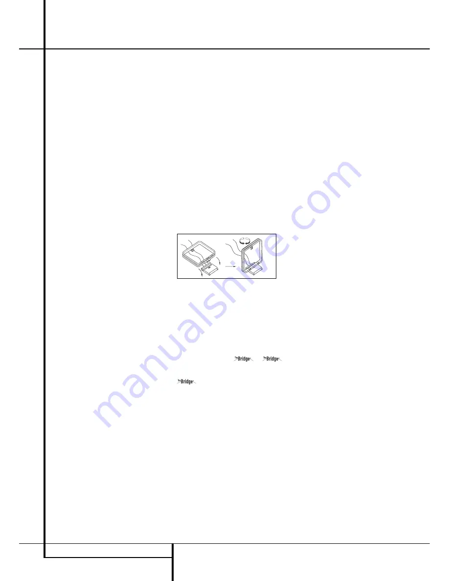
7. With the AVR 355 turned off, connect the
optional Harman Kardon 

to 

Digital Media Player (DMP) Connector

8

.

Your compatible Apple

®

iPod

®

may be docked in

when you wish to use it as your audio

source device.  This function is available on the
AVR 355 only. The AVR 255 features a STEREO
JACK Input instead to which all sorts of portable
devices can be connected via the headphone
output of such device.

8. Connect the front, center and  surround
 speaker  outputs 

DEFO

to the respective

speakers.

To assure that all the audio signals are carried to
your speakers without loss of clarity or
 resolution, we suggest that you use high-quality
speaker cable. Many brands of cable are
 available and the choice of cable may be
 influen ced by the distance between your
 speakers and the receiver, the type of speakers
you use,  personal preferences and other factors.
Your dealer or installer is a valuable resource to
 consult in selecting the  proper cable.

Regardless of the brand of cable selected, we
recommend that you use a cable constructed of
fine, multistrand copper with a cross-section
greater than 2 mm

2

.

Cable with a cross-section of 1.5 mm

2

may be

used for short runs of less than 4 m. We do not
recommend that you use cables with a cross-sec-
tion less than 1 mm

2

due to the power loss and

degradation in  per for mance that will occur.

Cables that are run inside walls should have the
appropriate markings to indicate listing with any
appropriate testing agency standards. Questions
about running cables inside walls should be
referred to your installer or a licensed electrician
who is familiar with the applicable local building
codes in your area.

When connecting wires to the speakers, be cer-
tain to observe proper polarity. Note that the
positive (+) terminal of each speaker connection
now carries a specific color code as noted on
page 8. However, most speakers will still use a
red terminal for the postive (+) connection.
Connect the “negative” or “black” wire to the
same terminal on both the receiver and the
speaker. 

NOTE:

While most speaker manufacturers

adhere to an industry convention of using black
terminals for negative and red ones for positive,
some manufacturers may vary from this
 configuration. To assure proper phase and
 optimal performance, consult the identification
plate on your speaker or the speaker’s manual to
verify polarity. If you do not know the polarity of
your speaker, ask your dealer for advice before
proceeding, or consult the  speaker’s
 manufacturer.

We also recommend that the length of cable
used to connect speaker pairs be identical. For
example, use the same length piece of cable to
connect the front-left and front-right or 
surround-left and surround-right speakers,
even if the speakers are a different distance
from the AVR.

Installation and Connections

16

INSTALLATION AND CONNECTIONS

Содержание AVR 355

Страница 1: ...AVR 255 AVR 355 Audio VideoReceiver OWNER S MANUAL Composit AVR Info Resolution Audio Effects Video Modes Surround Modes Back Exit Source List A B L K OK ENGLISH ...

Страница 2: ... Source Name 22 Zone 2 Audio 22 Speaker Setup EzSet EQ 22 Speaker Setup Manual 28 Operation 28 Surround Mode Chart 30 Basic Operation 30 Mute Function 30 Audio Effects 30 Video Modes 30 Source Selection 30 Video Input Selection 31 Video Troubleshooting Tips 31 Multichannel Disc Players with without HDMI 31 6 8 Channel Direct Input 31 Controls and Use of Headphones 31 Surround Mode Selection 32 Dig...

Страница 3: ...gs EzSet EQ also includes room equalization so that the signals sent to each speaker are tailored to provide accurate sonic quality with your specific combination of speaker type room size and other factors that influence room acoustics With EzSet EQ your system is custom configured in a few minutes with accu racy that previously required expensive and hard to use test equipment In tandem with EzS...

Страница 4: ...to this unit and or this unit may be exposed to liquid dripping or splashing On the top of this unit do not place Burning objects i e candles as they may cause fire damage to this unit and or personal injury Containers with liquid in them as they may fall and liquid may cause electrical shock to the user and or damage to this unit Do not cover this unit with a newspaper table cloth curtain etc in ...

Страница 5: ...ation for the component and in normal maintenance practices as your warranty will not cover this type of damage to furniture Cleaning When the unit gets dirty wipe it with a clean soft dry cloth If necessary wipe it with a soft cloth dampened with mild soapy water then a fresh cloth with clean water Wipe dry immediately with a dry cloth NEVER use benzene aerosol cleaners thinner alcohol or any oth...

Страница 6: ...Video Modes Button Source List Button Main Information Display Speaker Channel Input Indicator Surround Mode Button Back Exit Button Digital Optical Front Input Digital Coax Front Input Video Front Input Jacks Remote Sensor Window Composite Analog AVR Info Resolution Audio Effects Video Modes Surround Modes Back Exit Source List A B L K OK J C D 2 1 6 7 8 9 A E 4 5 B I G H 3 F 5 4 6 FRONT PANEL CO...

Страница 7: ... Main Information Display This display delivers messages and status indications to help you operate the receiver Speaker Channel Input Indicators These indicators are multipurpose indicating either the speaker type selected for each channel or the incoming data signal configuration The left center right right surround and left surround speaker indicators are composed of three boxes while the subwo...

Страница 8: ...tichannel input output and speaker connections all connection jacks and terminals have been color coded in conformance with the latest CEA standards as follows Front Left White Front Right Red Center Green Surround Left Blue Surround Right Gray Surround Back Left Brown Surround Back Right Tan Subwoofer LFE Purple Digital Audio Orange Composite Video Yellow Component Video Y Green Component Video P...

Страница 9: ...he black negative terminal on your speaker See page 16 for more information on speaker polarity F Surround Speaker Outputs Connect these outputs to the matching and terminals on your surround channel speakers In confor mance with the new CEA color code specifica tion the Blue terminal is the positive or terminal that should be connected to the red terminal on the Surround Left speaker with older c...

Страница 10: ... video source a HDMI Inputs Connect the HDMI output of video sources such as a DVD player set top box or HDTV tuner to either of these jacks b Zone 2 Outputs AVR 355 only Connect these jacks to an optional audio power amplifier to listen to the source selected by the multiroom system in a remote room c A BUS Connector Connect this jack to an optional A BUS certified remote room keypad or amplifier...

Страница 11: ...Button Back Exit Button Master Volume Disc Menu Button Mute Button Surround Mode Button Learn Button AVR 355 only Device Power OFF Button Device Power ON Button Transmitter Window OK Button Settings Button Zone Select Button Red Green Yellow Blue Color Buttons NOTE The function names shown here are each button s feature when used with the AVR Most buttons have additional functions when used with o...

Страница 12: ... serve as a ten button numeric keypad to enter tuner preset positions or track numbers with CD players changers or to tune stations directly Video Modes Button Press this button to go directly to the Video Modes Menu μ Menu Button When using a H K DVD play er with the receiver you can activate the DVD Menu with this button Ñ Activity Button This button may be pro grammed to transmit a series of co...

Страница 13: ...or that is connected to the Zone 2 jack V this button turns the Multi Room system off B AVR Settings Open the AVR settings info screen with this Button C Back Exit Button Press this button to go back to the previous Menu or to exit a Menu D Source Selectors Press these buttons to select an input source for theAVR 355 AVR 255 E Menu Navigation Buttons Use these buttons to move Up Down Left or Right...

Страница 14: ... Sleep time selection J Settings Info Button Open the Settings Info Menu for any Source with this Button K Menu Button When using a H K DVD player with the receiver you can activate the DVD Menu with this button L OK Button This button confirms settings and orders in the menus M Zone Select Buttons Press the Select Button to switch the Zone 2 Remote Control between Zone 1 function The white Button...

Страница 15: ...o display is not compatible HDMI Input Connections The different Version levels of HDMI define which type of audio signals it is compatible with Based on the lowest level of HDMI among your sources the connections to the AVR should be made as follows HDMI 1 0 sources carry digital video and multichannel or 2 channel PCM audio signals only Connect the HDMI output of a 1 0 source to either of the HD...

Страница 16: ...mble the AM Loop Antenna supplied with the unit as shown below Connect it to the AM and GND screw terminals 0 6 Connect the supplied FM antenna to the FM 75 ohm connection 1 The FM antenna may be an external roof antenna an inside powered or wire lead antenna or a connection from a cable system Note that if the antenna or connection uses 300 ohm twin lead cable you should use a 300 ohm to 75 ohm a...

Страница 17: ...input then select the 6 8 channel analog audio inputs and the AVR will retain the last video source you selected 1 Connect a VCR s audio and video Play Out jacks to the Video 2 and Analog 4 In jacks STon the rear panel The Audio and Video Record In jacks on the VCR should be connected to the Video 2 and Analog 4 Out jacks P7 on the AVR 2 Connect the digital audio outputs of a CD MD or DVD player s...

Страница 18: ...and AVR 355 Taking advantage of the AVR s built in seven channel amplifier it is possible to use two of the amplifi er channels to power speakers in the remote room When using this option you will not be able to use the full 7 1 channel capabilities of the AVR in the main listening room but you will be able to add another listening room without additional external power amplifiers To use the inter...

Страница 19: ...move things around until the system sounds correct Optimize your speakers so that audio transitions across the front of the room sound smooth When the AVR is used in 5 1 channel operation the preferred location for surround speakers is on the side walls of the room at or slightly behind the listening position In a 6 1 channel system a back surround speaker is required ide ally placed at the center...

Страница 20: ...PORTANT NOTE When viewing the on screen menus using a CRT based projector plasma display or any direct view CRT monitor or television it is important that they not be left on the screen for an extended period of time As with any video display constant display of a static image such as these menus or video game images may cause the image to be permanently burned into the CRT This type of damage is ...

Страница 21: ...epending on the number of channels desired and a virtual surround mode if your system uses fewer than the full complement of seven main speakers plus a subwoofer Digital surround signals such as Dolby Digital and DTS programs are automatically played in their native formats although you may change the surround mode at any time See the Advanced Functions section for information on surround modes av...

Страница 22: ...menus from view You are now ready to begin enjoying your new receiver Speaker Setup With EzSet EQ you are able to calibrate your sys tem in a fraction of the time it would take to enter the settings manually and with results that rival those achieved with expensive test equip ment and time consuming procedures The end result is a system calibration profile that enables your new receiver to deliver...

Страница 23: ...f you are uncomfortable with or cannot tolerate loud sounds and do not use some sort of ear protection we strongly recommend that you leave the room and ask someone else to run the EzSet EQ process or that you do not use EzSet EQ and enter the configuration settings manually as described on pages 24 through 27 Figure 8 Step 7 Once EzSet EQ has been started you will hear test signals circulate amon...

Страница 24: ...s which speakers the receiver will use to playback the low frequency bass portion of the source program If you send the lowest notes to small satellite speakers you won t hear these notes very well and you may even damage the speaker by exceeding its capabilities If you send the highest notes to the special purpose subwoofer you may not hear them at all With proper bass management the AVR 355 AVR ...

Страница 25: ... the seven crossover frequencies 40Hz 60Hz 80Hz 100Hz 120Hz 150Hz or 200Hz If the crossover frequency you determined in Step One is below 40Hz select the first option Large This set ting doesn t refer to the speaker s physical size but to its frequency response which is also called full range This means the speaker is capable of playing sounds throughout the fre quencyspectrum from the high pitche...

Страница 26: ... becomes both more critical and more complex Unlike the rotary balance control the goal of the AVR 355 AVR 255 s channel out put adjustment process is to examine the output level of each channel independently and ensure that each is heard at the listening position with equal loudness If you followed the instructions in the Initial Setup section then you let EzSet EQ handle this critical task for y...

Страница 27: ...ll automatically circulate to all channels pausing for a few moments at each channel and then moving to the next channel several seconds later as indicated by the highlight bar You may adjust the level for any channel when the test tone is paused there by using the M N Buttons You may also use the K L Buttons at any time to move the cursor to another line and the test tone will follow the cursor W...

Страница 28: ...ology that decodes full range discrete left MOVIE center right right surround and left surround channels from matrix surround encoded programs and conventional stereo sources MUSIC when an analog input or a digital input with PCM or Dolby Digital 2 0 recordings is in use The Dolby Pro Logic II Movie mode is DOLBY PRO LOGIC optimized for movie soundtracks that are recorded with matrix surround by c...

Страница 29: ... Wide Reference Mode the apparent width of the sound across the front image is defined by the distance between the two speakers The Wide Mode provides a wider more spacious front image when the two speakers areclose together THEATER The THEATER mode creates a 5 1 or 6 1 sound field that resembles the acoustic feeling of a standard live performance theater with stereo and even pure mono sources HAL...

Страница 30: ... on the specific characteristics of your listening room you may wish to tweak some of the audio settings such as tone controls to improve performance Access these settings from the Audio Effects Button 9D as described in the Advanced Functions section It is not necessary to adjust the Audio Effects settings to enjoy your new AVR We recommend leaving the settings at their default values until you a...

Страница 31: ...analog audio outputs but not via its HDMI output Controls and Use of Headphones Adjust the volume to a comfortable level using the front panel Volume Control 1 or remote Volume Up Down P buttons To temporarily silence all speaker outputs press the Mute button R on the Remote Control This will interrupt the output to all speakers and the headphone jack but it will not affect any recording or dubbin...

Страница 32: ...s Digital audio signals offer the benefit of greater capacity which allows recording artists to encode center and surround channel information directly into the signal The result is improved sound quality and startling directionality since each of these channels is reproduced discretely Alternatively the artist may encode only two channels but the digital signal allows for a higher sampling rate t...

Страница 33: ...d by the Dolby Pro Logic decoder in the AVR By default these signals are played in Dolby Pro Logic IIx Movie mode but you may select another Dolby surround mode manually Surround Modes Surround mode selection is dependent upon the format of the incoming audio signal as well as personal taste There is no harm in experimenting with all of the modes available with any given source material Informatio...

Страница 34: ...back of audio video and still image materials on your iPod through your high quality audio video system Pressing the DMP Selector Button C will also activate the AVR remote s control codes for the iPod and you may also use the front panel controls to operate the iPod When The Bridge is properly connected and a compatible iPod is properly docked the Upper Display Line will read DMP CONNECTED Once t...

Страница 35: ...e AVR needs to be configured for multiroom operation using the steps below Press the AVR button Y to bring the main menu to the screen Press the Button F until the ZONE 2 menu line is highlighted in blue Press the OK button X to enter the menu Figure 18 When the ZONE 2 menu appears the blue cursor bar will be at the Status Off line Since this line is used to turn the system on and off do not make ...

Страница 36: ...io power amplifier connected to the Zone 2 Output jacks b Although changes to the input source or Zone 2 volume will normally be made using an IR sensor in the remote room that is connected to the AVR it is also possible to change those settings from the main listening room This is useful for situations where some or all of the remote rooms do not have an IR sensor or to take control over the remo...

Страница 37: ...ow the image pillarboxing When displaying full screen images on a widescreen device black or gray bars may appear to the left and right of the image Some displays especially plasma and CRT monitors may suffer from burn in when the same image such as the horizontal or vertical bars is left on screen for a long period of time Use this setting to adjust the picture so that it fills the display s scre...

Страница 38: ...s equipped with a number of advanced features that add extra flexibility to the unit s operation While it is not necessary to use these features to operate the unit they provide additional options that you may wish to use System Settings The AVR 255 AVR 355 offers system settings that allow you to make the receiver easier to use rather than directly affecting performance These settings may be acce...

Страница 39: ...ar them We recommend setting some timeout period to avoid the possibility of burn in damage to plasma or CRT displays Screen Saver Use this setting to program a timeout period for no activity with no menus displayed before the AVR s built in screen saver begins Select a period of 5 the default 10 or 20 minutes or turn off the screen saver We recommend setting some timeout period to avoid the possi...

Страница 40: ...he desired station has been tuned press the OK Button and two dashes will flash in the front panel display Use the Numeric Keys to enter the desired preset number and confirm with the OK Button If the preset number is higher than 9 press the 0 Button on the Remote K first to access two digit numbers If you do not press this button first you can only enter single digit numbers To tune a preset stat...

Страница 41: ...orts EDUCATE Educational DRAMA Drama CULTURE Culture SCIENCE Sciencek VARIED Varied Speech Programs POPM Popular Music ROCKM Rock Music M O R M Middle of the Road Music LIGHTM Classical Music CLASSICS Serious Classical Music OTHERM Other Music WEATHER Weather Information FINANCE Financial Programs CHILDREN Children s Programs SOCIAL A Social Affairs Programs RELIGION Religious Broadcasts PHONE IN ...

Страница 42: ...different remote code 7 If the unit does not react to any code entered if the code for your product does not appear in the tables in the separate setup code guide or if not all functions operate properly try programming the remote with the Auto Search Method Auto Search Method If the unit you wish to include in the AVR s remote is not listed in the code tables in the separate setup code guide or i...

Страница 43: ...he original remote that you wish to teach into the AVR 355 remote When the Input Button on the AVR 355 blinks 3 times the code has been learned 6 Repeat steps 4 though 5 for each button on the source remote that you wish to transfer to the AVR 355 remote 7 Once all codes have been transferred from the original source remote to the AVR 355 remote press the Learn button t The Input Button blinks 3 t...

Страница 44: ...to change to the DVD mode Press the DEVICE POWER ON button to turn on the DVD Press the SAT device button to change to the SAT mode Press the DEVICE POWER ON button to turn on the SAT receiver 10 Press the ACTIVITY button After following these steps each time you press the Activity Button n followed by pressing the 2 Button where the Activity is pro grammed the remote will send all Power On comman...

Страница 45: ...urce Selector will light go dark and then light up again indicating the remote is in Program mode and that you may release the button 2 Select the type of punch through program ming a To program channel control punch through press the Channel Up Button b To program transport control punch through press the Play Button 3 Press the Source Selector for the device whose channel or transport controls y...

Страница 46: ...0 0 0 0 0 0 27 Activity 28 Back Exit Back Exit Back Exit Back Exit Back Exit Back Exit Clear 29 Menu Menu Menu Menu Menu Menu Disc Menu 30 Light 31 Disc Menu Disc Menu 32 Left Left Left Left Left Left Left 33 Right Right Right Right Right Right Right 34 OK OK OK OK OK OK Enter 35 Up Up Up Up Up Up Up 36 Down Down Down Down Down Down Down 37 Red Angle 38 Green Subtitle 39 Yellow Audio 40 Blue Zoom ...

Страница 47: ...6 6 6 6 6 6 6 6 6 6 22 7 7 7 7 7 7 7 7 7 7 23 8 8 8 8 8 8 8 8 8 8 24 9 9 9 9 9 9 9 9 9 9 25 Back Enter Prev Ch Instant Replay 26 0 0 0 0 0 0 0 0 0 0 27 28 Exit Return Back Exit Clear Exit Cancel Exit Clear 29 EZRecord Source Menu Menu Menu Start Menu Menu Menu 30 31 Disc Menu Disc Menu Disc Menu DVD Menu Osd Av 32 Left Left Left Left Left Left Left Left Left 33 Right Right Right Right Right Right ...

Страница 48: ... 2 2 2 2 17 3 3 3 3 3 3 3 18 4 4 4 4 4 4 4 19 5 5 5 5 5 5 5 20 6 6 6 6 6 6 6 21 7 7 7 7 7 7 7 22 8 8 8 8 8 8 8 23 9 9 9 9 9 9 9 24 Last Last Last Last Last 25 0 0 0 0 0 0 0 26 Activity 27 Back Exit Back Exit Back Exit Back Exit Back Exit Clear Exit 28 Menu Menu Menu Menu Menu Disc Menu EZRecord 29 Disc Menu Disc Menu Disc Menu 30 Left Left Left Left Left Left Left 31 Right Right Right Right Right ...

Страница 49: ...5 5 5 5 5 20 6 6 6 6 6 6 6 6 6 21 7 7 7 7 7 7 7 7 7 22 8 8 8 8 8 8 8 8 8 23 9 9 9 9 9 9 9 9 9 24 Back Enter Prev Ch Instant Replay 25 0 0 0 0 0 0 0 0 0 26 27 Return Back Exit Clear Exit Cancel Exit Clear 28 Source Menu Menu Menu Start Menu Menu Menu 29 Disc Menu Disc Menu DVD Menu Osd Av 30 Left Left Left Left Left Left Left Left 31 Right Right Right Right Right Right Right Right 32 Enter Enter OK...

Страница 50: ... Power Make certain AC power cord is plugged Power Switch 1 is pushed into a live outlet Check to see if outlet is switch controlled Display lights but no sound Intermittent input connections Make certain that all input and speaker or picture connections are secure Mute is on Press Mute button G Volume control is down Turn up volume control No sound from any speaker Amplifier is in protection mode...

Страница 51: ...0W maximum AVR 355 Standby 3W 890W maximum 7 channels driven Dimensions Max Width 440mm Height 165mm Depth 382mm Weight net AVR 255 14 0 kg AVR 355 14 4 kg Depth measurement includes knobs buttons and terminal connections Height measurement includes feet and chassis All features and specifications are subject to change without notice Harman Kardon The Bridge and Logic 7 are registered trademarks o...

Страница 52: ...alog 4 inputs and outputs Composite OR S Video 2 input Coaxial Output and output Portable audio player AUX Any Stereo Jack use mini plug Not required cable not included Make this connection only when using the TV source for a non display device Do not connect your television s or video display s video output to the AVR at any time 52 APPENDIX APPENDIX SETTINGS WORKSHEET Table A2 Source Setting Def...

Страница 53: ...t Level 0dB 0dB Surround Right Level 0dB 0dB Surround Back Right Level 0dB 0dB Surround Back Left Level 0dB 0dB Surround Left Level 0dB 0dB Sub Level 0dB 0dB Note The 6 8 Channel Inputs are direct inputs whose signals are passed directly to the volume control without any bass management processing Thus the speakers are always full range and cannot be adjusted The settings are global for the remain...

Страница 54: ...ness 50 Contrast 50 Color 50 Sharpness 50 Picture Adjust Auto Fit Noise Reduction 0ff MPEG Noise Reduction 0ff Cross Color Suppressor Off Film Mode Detect Off Note These settings are only available when the Video Mode is set to Custom Note These settings are only displayed when Advanced Video Settings is selected Table A5 Source Settings Cable Sat DVD Media Server Radio TV Game AUX Surround Modes ...

Страница 55: ... available when Dolby Pro Logic II or IIx Music mode has been selected Access these settings by selecting the Edit option Table A9 Remote Control Codes Source Input Device Type if changed Product Code Cable Sat DVD Media Server TV Game AUX Table A10 System Settings Feature Default Your Setting Front Panel Dimmer On 100 Volume Units dB Volume Default Off Volume Default Level 25dB Unit of Measure Fe...

Страница 56: ...56 APPENDIX APPENDIX SETTINGS WORKSHEET Table A11 Zone 2 Settings Source Input Device Type if changed Your Settings Status Off Source Cable Sat Volume 25dB Surround Back Amps Main Room ...

Страница 57: ...APPENDIX 57 ENGLISH APPENDIX SETTINGS WORKSHEET ...

Страница 58: ...250 Crossways Park Drive Woodbury New York 11797 www harmankardon com Harman Consumer Group Inc 2 route de Tours 72500 Château du Loir France 2008 Harman Kardon Incorporated Part No CQX1A1318Z ...

Отзывы: