Harman Kardon AVR 2700 Скачать руководство пользователя страница 16

16

AVR

Types of Home Theater System Connections

Radio Connections

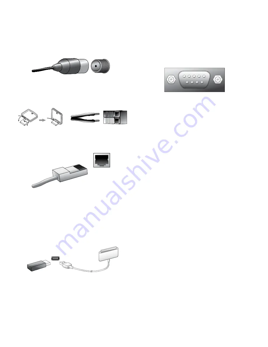
Your AVR uses separate terminals for the included FM and AM antennas. The FM antenna 
uses a 75-ohm F-connector.

The AM antenna connector uses spring-clip terminals. After assembling the antenna as 
shown below, press the levers to open the connectors, insert the bare wires into the 
openings, and release the levers to secure the wires. The antenna wires are not polarized, 
so you can insert either wire into either connector.

Network Connector

The AVR’s Network connector allows you to enjoy Internet radio or content from other 
DLNA-compatible devices that are connected to the same network. Use a Cat. 5 or  
Cat. 5E Ethernet cable to connect the AVR’s RJ-45 connector to your home network.

USB Port

The AVR can play audio files from an Apple iOS

®

 device connected to the USB port, 

and allows you to control the iOS device via the AVR remote control. The AVR can also 
play MP3 and WMA audio files from a USB device inserted into the USB port. Insert the 
connector or device into the USB port oriented so it fits all the way into the port. You may 
insert or remove the connector or device at any time – there is no installation or ejection 
procedure.

The USB port on your AVR is also used to perform firmware upgrades. If an upgrade for 
the AVR’s operating system is released in the future, you will be able to download it to the 
AVR using this port. Complete instructions will be provided at that time.

IMPORTANT: Do not connect a PC or other USB host/controller to the AVR’s USB 
port, or you may damage both the AVR and the other device.

RS-232 Connector

Your AVR’s RS-232 serial port may be connected to an external control system to allow 
it to transmit control commands to the AVR. The port is bidirectional so that the AVR 
can transmit status updates to the control device. Connecting and using the RS-232 
port requires considerable technical knowledge and is best left to a professional custom 
installer.


Содержание AVR 2700

Страница 1: ...Audio video receiver AVR 3700 AVR 370 AVR 2700 AVR 270 Owner s Manual...

Страница 2: ...0 CONNECT TO YOUR HOME NETWORK 20 CONNECT THE RADIO ANTENNAS 20 INSTALL A MULTIZONE SYSTEM 21 CONNECT IR EQUIPMENT AVR 3650 AVR 365 ONLY 22 CONNECT THE TRIGGER OUTPUT 23 CONNECT TO AC POWER 23 SET UP...

Страница 3: ...devices do not run power cords under rugs or carpets or place heavy objects on them Damaged power cords should be replaced immediately by an authorized service center with a cord meeting factory speci...

Страница 4: ...e Knob Video Modes Button Setup Button IR Sensor Power Button Left Right Buttons Headphone Jack EzSet EQ Mic Input Back Exit Button Resolution Button Audio Effects Button Surround Modes Button Up Down...

Страница 5: ...iver is installed inside of a cabinet connect an optional infrared receiver to the Remote IR In connector on the AVR s rear panel Volume knob Turn this knob to raise or lower the volume Headphone jack...

Страница 6: ...tors Analog Video Connectors Wi Fi Antenna Connector AVR 3700 AVR 370 Pre Out Connectors AVR 3700 AVR 370 Subwoofer Connector Radio Antenna Connectors Speaker Connectors Digital Audio Connectors Fan V...

Страница 7: ...g audio connectors are provided s Analog Audio Input connectors Use the AVR s Analog Audio Input connectors for source devices that don t have HDMI or digital audio connectors See Connect Your Audio a...

Страница 8: ...s Mute Button Info Button AVR Button Zone Selector Switch OK Button Last Channel Button Video Modes Button IR Transmitter Device Power On Off Buttons Surround Modes Button Number Buttons Activity Butt...

Страница 9: ...urround mode options Press the OK button or press the Back Exit button to exit the Surround Modes menu and display the next higher menu in the hierarchy See the Advanced Functions section on page 33 f...

Страница 10: ...l Functions AVR 3700 AVR 370 only IR Transmitter Lens Source Selector Buttons Mute Button Sleep Button Menu Button Up Down Left Right Buttons Volume Up Down Buttons Transport Control Buttons AVR Butto...

Страница 11: ...source device than that for the main room but not different tuner bands If you select the same source as that for the main room any commands sent to the source device will affect both zones s The rst...

Страница 12: ...akers you cannot use both The surround back channel speakers are optional If your system does not include surround back left and right speakers you can set up your AVR with a 5 1 channel surround soun...

Страница 13: ...aker directly to either side of the listening position Place the surround back left and right speakers 150 degrees from the center speaker directly facing the opposite side front speaker You should pl...

Страница 14: ...s purple subwoofer output looks similar to a full range analog audio jack it is ltered so that only the low frequencies pass through it Don t connect this output to any device other than a subwoofer...

Страница 15: ...Many source devices output both audio and video signals e g Blu ray Disc DVD player cable television box HDTV tuner satellite box VCR DVR In addition to an audio connection as described above make a...

Страница 16: ...ce via the AVR remote control The AVR can also play MP3 and WMA audio les from a USB device inserted into the USB port Insert the connector or device into the USB port oriented so it ts all the way in...

Страница 17: ...woofers See Manual Speaker Setup Number of Speakers on page XX for information about activating the two subwoofer outputs Consult your subwoofer s user manual for speci c information about making conn...

Страница 18: ...r source devices as you wish and re assign any of the input connections to any of the Source Buttons listed in the table according to where you actually connect each of your source devices As you conn...

Страница 19: ...ponent Video Equipped Source Device Component Video Cable not supplied To Component Video Outputs Connect Your Composite Video Devices Use composite video connectors for video source devices that don...

Страница 20: ...s Connect Your Video Recorder Connect an analog video recorder s video input connector to the AVR s Composite Monitor Out connector You can record any composite video signal To record the audio from t...

Страница 21: ...e appropriate safety codes when installing concealed wiring particularly all applicable building codes Failure to do so may present a safety hazard If you have any doubt about your ability to work wit...

Страница 22: ...Theater Speaker System Zone 2 Ampli er not supplied FL SL SR FR LFE SBL SBR C AVR Speaker Wire not supplied Speaker Wire not supplied Zone 2 Main Room Connect IR Equipment The AVR is equipped with Rem...

Страница 23: ...rce device is shared with the main listening area any control commands issued to that source will also affect the main room Connect the Trigger Output If your system has equipment that can be controll...

Страница 24: ...of the codes in the remote s library for dervices of its type by pressing the remote s Up button repeatedly until the device turns off When it does press the Source Selector button to save the code 5...

Страница 25: ...ce then press and hold the Learn button until the Source Selector button glows red The remote is now in the Learning mode 3 On the AVR remote choose a destination button that will learn the source dev...

Страница 26: ...con guration options Depending on the resolution selected the menus shown by your system may vary in appearance from the illustrations The Main Menu system consists of six submenus Source Select Setup...

Страница 27: ...urce IMPORTANT The Video Input from Source Audio Input from Source and Resolution to Display settings are not optional and must be adjusted before you use your AVR to enable playback of each source Yo...

Страница 28: ...ting 3D video content it will not automatically switch out of the bypass mode when it detects conventional 2D video content To turn the HDMI Bypass off you must cycle the AVR into the Standby mode and...

Страница 29: ...twork Setup AVR AP Mode The following options appear in the Wireless Setup menu s Search AP Select this option to display and select the wireless network you wish to join s Information Select this opt...

Страница 30: ...r volume levels often used in the home When the Modeler module is active you may notice details of the performance that were hidden when the program was played on other equipment To adjust the Dolby V...

Страница 31: ...of some actions such as input switching or switching between SD and HD channels Listening to FM and AM Radio Select the Radio source A screen similar to the one in the illustration below will appear A...

Страница 32: ...m order press the Menu button and select the Random Music setting Each press of the OK button turns the setting on or off The AVR will automatically repeat the tracks until playback is stopped manuall...

Страница 33: ...to the Internet via the www radioharmankardon com portal To select a stream press the Menu button and use the Up Down buttons to search by category Presets My Favourites Added Stations Location Genre...

Страница 34: ...Music or Logic 7 Game mode depending on the source Virtual Surround When only two main speakers are present in the system you can use HARMAN Virtual Surround to create an enhanced sound eld that virtu...

Страница 35: ...d the number of channels which is displayed brie y as three numbers separated by slashes e g 3 2 1 The rst number indicates the number of front channels in the signal 1 represents a monophonic recordi...

Страница 36: ...les the setting On or Off Tone Control This setting determines whether the treble and bass controls are active When it s set to Off the tone controls are out of the circuit with no changes to the soun...

Страница 37: ...ment Color Adjustment 1 When the brightness and contrast are set optimally adjust the Color control Set the level so that the colors look strong but still natural not overdone If the color level is to...

Страница 38: ...ers and all information below the crossover point is played through the subwoofer This way each loudspeaker in your system will perform at its best delivering a more powerful and enjoyable sound exper...

Страница 39: ...en you have nished entering the settings select Back or press the Back Exit button Sub Mode Move the cursor to the Sub Mode line This setting depends upon the Crossover setting you selected for the fr...

Страница 40: ...the current speaker until you use the Up Down buttons to move it to another speaker Use the Left Right buttons to adjust the level for the speaker through which the test tone is playing If you are usi...

Страница 41: ...rce set to the digital input Notes about listening in Zone 2 s Although you can listen to iPod as a source in Zone 2 you cannot begin iPod playback from within Zone 2 You must initially select iPod as...

Страница 42: ...automatically turn the AVR on NOTE The connected TV must support the HDMI System Standby CEC Consumer Electronics Control TV Control This setting extends some audio control functions between the AVR a...

Страница 43: ...Video Modes and Audio Effects menus remain visible after the last adjustment 5 seconds 10 seconds 30 seconds 1 minute or 5 minutes Select No Time Out to view the menus inde nitely but this setting is...

Страница 44: ...e Selector button or the Setup button will ash three times It isn t possible to edit a command within a Macro To erase the Macro 1 Press and hold the Activity Button and the button into which you prog...

Страница 45: ...oes not respond to remote control commands s 7EAK BATTERIES IN REMOTE s 2EMOTE SENSOR IS OBSCURED s HANGE BATTERIES IN REMOTE s NSURE THAT THE 62 S FRONT PANEL REMOTE SENSOR IS IN the line of sight of...

Страница 46: ...y IHF 1 3 V 13 2dBf Signal to noise ratio mono stereo 70dB 68dB Distortion mono stereo 0 2 0 3 Stereo separation 40dB 1kHz Selectivity 400kHz 70dB Image rejection 80dB IF rejection 80dB AM Tuner Secti...

Страница 47: ...log 1 or 2 Inputs and Rec Out Composite Video 2 Input and Monitor Output iPod or iPhone USB iPod USB N A N A DVR DVR HDMI 5 Analog 1 or 2 HDMI 5 Table A2 Source Setting Defaults Cable Sat Disc Media S...

Страница 48: ...bwoofer Mode LFE Subwoofer Size 100Hz Front Left Level 0dB Center Level 0dB Front Right Level 0dB Surround Right Level 0dB Surround Back Right Front Height Right Level 0dB Surround Back Left Front Hei...

Страница 49: ...Pod iPhone Surround Modes Video Input N A N A Audio Input USB N A Resolution to Display Adjust Lip Sync Change Name N A N A Zone 2 Audio USB Dolby Volume Table A6 Audio Effects Settings Default Cable...

Страница 50: ...Custom Note These settings are displayed only when Advanced Video Settings is selected Table A8 Surround Modes Default Cable Sat Disc Media Server Radio TV USB Network Game AUX iPod DVR Auto Select L...

Страница 51: ...Off TV Control Off Network Settings Automatic Volume Units dB Volume Default Off Volume Default Level 25dB Unit of Measure Feet AVR 3700 AVR 2700 Meters AVR 370 AVR 270 Language English Dolby Volume...

Страница 52: ...of Dolby Digital materials s OLBY IGITAL OR OR OR 2 1 0 or 1 2 2 0 or 1 3 2 0 or 1 s OLBY IGITAL 8 Dolby Pro Logic II Mode Group Analog decoder that derives five full range discrete main audio channel...

Страница 53: ...OR OR OR OR OR 3 2 0 or 1 s 43 3 ATRIX PLAYED AS s 43 3 ISCRETE PLAYED AS DTS HD DTS HD is a new high definition audio format that complements the high definition video found on Blu ray Disc and HD DV...

Страница 54: ...lly suited to two channel sources containing Dolby Surround or matrix encoding Logic 7 Movie mode increases center channel intelligibility The AVR is programmed at the factory to default to this mode...

Страница 55: ...28 29 30 31 32 33 34 35 37 38 36 39 44 43 46 47 48 45 40 41 42 4 5 6 7 8 9 10 15 18 19 20 16 17 11 12 13 14 54 55 56 57 58 51 50 49 53 52 Refer to the numbered buttons when using the Function List in...

Страница 56: ...6 6 6 6 6 6 6 6 24 7 7 7 7 7 7 7 7 7 25 8 8 8 8 8 8 8 8 8 26 9 9 9 9 9 9 9 9 9 27 Last Last Last Last Last Prev Ch Last 28 0 0 0 0 0 0 0 0 0 29 Activity Activity Activity Activity Activity Activity Ac...

Страница 57: ...8 8 8 26 9 9 9 9 9 9 9 9 27 Last Prev Ch Enter Prev Ch Instant Replay Enter Last 28 0 0 0 0 0 0 0 0 29 Activity Activity Activity Activity Activity Activity Activity Activity 30 Back Exit Bypass Clear...

Страница 58: ...ATIONAL 148 177 179 180 181 182 NEC 010 115 121 123 125 OLEVIA 007 Refer to Tables A14 through A24 when programming the codes for your components into the remote TV Manufacturer Brand Setup Code Numbe...

Страница 59: ...JVC 318 348 411 432 KENWOOD 320 348 LG GOLDSTAR 318 407 LLOYD 340 LXI 320 340 MAGNAVOX 340 MARANTZ 318 MEMOREX 317 320 340 352 353 354 376 442 MGA 349 MITSUBISHI 349 431 MULTITECH 340 NAD 439 VCR Manu...

Страница 60: ...138 149 209 PIONEER 071 094 100 112 123 131 161 162 215 PROTON 210 RADIO SHACK 126 166 213 CD Manufacturer Brand Setup Code Number RCA 024 081 093 150 REALISTIC 058 093 095 104 105 108 164 166 SANSUI...

Страница 61: ...COM 330 333 390 391 393 409 TOSHIBA 302 426 460 461 462 470 UNIDEN 323 332 348 349 350 351 354 355 381 383 389 403 466 479 480 ZENITH 359 384 385 387 394 419 488 Table A20 Remote Control Product Codes...

Страница 62: ...42 113 VIDEOWAY 124 211 VIEWSTAR 019 025 053 086 089 190 ZENITH 065 125 211 219 Table A22 Remote Control Product Codes Media Server Manufacturer Brand Setup Code Number APPLE 008 009 BEYOND 003 ESCIEN...

Страница 63: ...nse under U S Patent s 5 451 942 5 956 674 5 974 380 5 978 762 6 226 616 6 487 535 7 003 467 and other U S and worldwide patents issued and pending DTS DTS ES and DTS Neo 6 are registered trademarks a...

Отзывы: