


21
SYSTEM CONFIGURATION
When all speaker selections have been made,
press the
¤
Button
q
until the on-screen
›
cursor points to
RETURN TO MENU
and
press the
Set Button
o
to return to the
MASTER MENU
.
The Speaker Configuration may also be
changed at any time without using the full-OSD
on-screen menu system by pressing the
Speaker Select
button on the front panel
ı
or remote
. Once the button is pressed,
FNT SPEAKER
will appear in both the
lower third of the video display and the
Main
Information Display
S
.
Within three seconds, press either the front
panel
‹
/
›
Selector Buttons
5
or the
⁄
/
¤
Buttons
mq
on the remote to select a dif-
ferent speaker position, or press the
Set
Button
Ôo
to begin the adjustment
process for the front left and right speakers.
When the
Set Button
Ôo
has been
pressed and the system is ready for a change to
the speaker setting, the on-screen display and
Main Information Display
S
will read
FNT LARGE
or
FNT SMALL
, depend-
ing on the current setting. Press the front panel
‹
/
›
Selector Buttons
5
or the
⁄
/
¤
Buttons
mq
on the remote until the
desired setting is shown, using the instructions
for “large” or “small” shown earlier.
If the configuration for another speaker position
needs to be changed, press the front panel
‹
/
›
Selector Buttons
5
or the
⁄
/
¤
Buttons
mq
on the remote to select a different
speaker position, and then press the front panel
‹
/
›
Selector Buttons
5
or the
⁄
/
¤
Buttons
mq
on the remote until the cor-
rect speaker setting is shown.
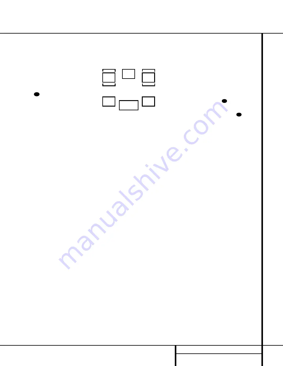
To assist in making speaker configuration set-
tings, the icons in the
Speaker/Channel
Input Indicators
L
change as the speaker
type is selected at each position. When only the
center icon box containing the abbreviation for
the speaker position is lit, the speaker is set for
“small.” When the inner box and the two outer
boxes with circles inside them are lit, the
speaker is set for “large.” When no indicator
appears at a speaker location, that position is
set for “none” or “no” speaker.
NOTE:
These icons are available only when
making setup changes in the semi-OSD mode.
For example, in Figure 6, the left front and right
front speakers are set for “large,” the center,
left surround (LS) and right surround (RS)
speakers are set for small, and a subwoofer is
set, as shown by the box with the abbreviation
“LFE”, which stands for “low-frequency
effects.”
Figure 6
Output Level Adjustment
Output level adjustment is a key part of the
configuration process for any surround-sound
product. It is particularly important for a Dolby
Digital receiver such as the AVR 220, as
correct outputs will ensure that you hear
sound tracks with the proper directionality
and intensity.
IMPORTANT NOTE:
Listeners are often
confused about the operation of the surround
channels. While some assume that sound
should always be coming from each speaker,
most of the time there will be little or no
sound in the surround channels. This is because
they are only used when a movie director or
sound mixer specifically places sound there to
create ambience, a special effect or to continue
action from the front of the room to the rear.
When the output levels are properly set it is
normal for surround speakers to operate only
occasionally. Artificially increasing the volume
to the rear speakers may destroy the illusion
of an enveloping sound field that duplicates
the way you hear sound in a movie theater or
concert hall.
Before beginning the output level adjustment
process, make certain that all speaker connec-
tions have been properly made. The system
volume should be set to the level that you will
use during a typical listening session. Finally,
make certain that the
Balance Control
*
is
set to the center “12 o’clock” position.
Using EzSet
Harman Kardon’s exclusive EzSet remote makes
it possible to quickly and accurately set the
AVR 220’s output levels without the use of a
sound pressure meter, although manual adjust-
ment is also available. However, for the easiest
setup, follow these steps while seated in the
listening position that will be used most often:
1. Make certain that all speaker positions
have been properly configured for their
“large” or “small” settings (as outlined
above) and turn off the OSD system if it is
in use.
2. Adjust the volume so that it is at
-15dB
, as shown in the on-screen dis-
play or
Main Information Display
S
.
3. Hold the remote in front of you at arm’s
length, being sure not to cover the
EzSet
Sensor Microphone
at the top of
the remote.
4. Press and hold the
SPL Button
for
three seconds. Release the button when
the
Program/SPL Indicator
c
stops
flashing and you hear the test noise from
the front left speaker.
5. At this point, the EzSet circuitry will take
over, adjusting the output level of each
channel so that when the process is com-
plete all levels will be equal and at the set
reference point. This process may take a
few minutes, depending on the extent of
adjustment required.
6. During the adjustment process, you will see
the location of the channel position being
adjusted appear in both the on-screen
display (if connected) and the
Main
Information Display
S
, alternating with
a readout of the output setting, relative to
the reference volume level. As the adjust-
ment proceeds, a few things will happen
simultaneously:
• The channel position being adjusted will
flash in the
Speaker/Channel Input
Indicators
L
. If the test noise is heard
from a channel other than the one shown
in the indicator, there is an error in the
speaker connections. If this is the case,
press the
Test Button
h
TWICE to
stop the adjustment. Then, turn the unit
off and verify that all speakers are con-
nected to the proper
Outputs
›fi
.
• As each channel is set, the channel name
and the adjustment offset will appear in
the on-screen display (if connected) and
the
Main Information Display
S
.
While the level is changing, the
Program/SPL Indicator
c
will
change colors to reflect the output level
in relation to the reference. A red indica-
tion shows that the level is too high,
while an amber indication shows that the
level is too low. When the indicator is
green, the level is correct, and the test
36
39
NIGHT
L
R
C
SL
SR
LFE
32
System Configuration
Содержание AVR 220
Страница 1: ...AVR 220 Audio VideoReceiver OWNER S MANUAL Power for the Digital Revolution ...
Страница 51: ...51 NOTES Notes ...


