background image

M24C64, M24C32

8/26

DEVICE OPERATION 

The device supports the I

2

C protocol. This is sum-

marized in 

Figure 5.

. Any device that sends data

on to the bus is defined to be a transmitter, and
any device that reads the data to be a receiver.
The device that controls the data transfer is known
as the bus master, and the other as the slave de-
vice. A data transfer can only be initiated by the
bus master, which will also provide the serial clock
for synchronization. The M24Cxx device is always
a slave in all communication.
Start Condition
Start is identified by a falling edge of Serial Data
(SDA) while Serial Clock (SCL) is stable in the
High state. A Start condition must precede any
data transfer command. The device continuously
monitors (except during a Write cycle) Serial Data
(SDA) and Serial Clock (SCL) for a Start condition,
and will not respond unless one is given.
Stop Condition
Stop is identified by a rising edge of Serial Data
(SDA) while Serial Clock (SCL) is stable and driv-
en High. A Stop condition terminates communica-
tion between the device and the bus master. A
Read command that is followed by NoAck can be
followed by a Stop condition to force the device
into the Stand-by mode. A Stop condition at the
end of a Write command triggers the internal Write
cycle.
Acknowledge Bit (ACK)
The acknowledge bit is used to indicate a success-
ful byte transfer. The bus transmitter, whether it be
bus master or slave device, releases Serial Data
(SDA) after sending eight bits of data. During the
9

th

 clock pulse period, the receiver pulls Serial

Data (SDA) Low to acknowledge the receipt of the
eight data bits.
Data Input
During data input, the device samples Serial Data
(SDA) on the rising edge of Serial Clock (SCL).
For correct device operation, Serial Data (SDA)
must be stable during the rising edge of Serial
Clock (SCL), and the Serial Data (SDA) signal
must change 

only

 when Serial Clock (SCL) is driv-

en Low.
Memory Addressing
To start communication between the bus master
and the slave device, the bus master must initiate
a Start condition. Following this, the bus master
sends the Device Select Code, shown in 

Table 3.

(on Serial Data (SDA), most significant bit first).
The Device Select Code consists of a 4-bit Device
Type Identifier, and a 3-bit Chip Enable “Address”
(E2, E1, E0). To address the memory array, the 4-
bit Device Type Identifier is 1010b.
Up to eight memory devices can be connected on
a single I

2

C bus. Each one is given a unique 3-bit

code on  the Chip Enable (E0, E1, E2) inputs.
When the Device Select Code is received, the de-
vice only responds if the Chip Enable Address is
the same as the value on the Chip Enable (E0, E1,
E2) inputs.
The 8

th

 bit is the Read/Write bit (RW). This bit is

set to 1 for Read and 0 for Write operations.
If a match occurs on the Device Select code, the
corresponding device gives an acknowledgment
on Serial Data (SDA) during the 9

th

 bit time. If the

device does not match the Device Select code, it
deselects itself from the bus, and goes into Stand-
by mode.

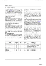
Table 6. Operating Modes

Note: 1. X = 

V

IH 

or V

IL

.

Mode

RW bit

WC

 1

Bytes

Initial Sequence

Current Address Read

1

X

1

START, Device Select, RW = 1

Random Address Read

0

X

1

START, Device Select, RW = 0, Address

1

X

reSTART, Device Select, RW = 1

Sequential Read

1

X

 1

Similar to Current or Random Address Read

Byte Write

0

V

IL

1

START, Device Select, RW = 0

Page Write

0

V

IL

≤ 

32

START, Device Select, RW = 0

harman/kardon

AVR 155/230 Service Manual

Page 58 of 92

Содержание AVR 155/230

Страница 1: ...ROCESSOR RESET 5 PACKAGE LIST AND PARTS 6 DISASSEMBLY 7 EXPLODED VIEW AND PARTS 8 ELECTRICAL PARTS LIST 9 SEMICONDUCTOR PINOUTS 35 PCB DRAWINGS 76 BLOCK DIAGRAM 82 WIRING DIAGRAM 83 AMP BIAS ADJUSTMEN...

Страница 2: ...er to the unit under test 2 After removing an electrical assembly equipped with ES devices place the assembly on a conductive surface such as aluminum foil to prevent electrostatic charge build up or...

Страница 3: ...eo Section Video Format PAL NTSC Input Level Impedance 1Vp p 75 ohms Output Level Impedance 1Vp p 75 ohms Video Frequency Response Composite and S Video 10Hz 8MHz 3dB Video Frequency Response Componen...

Страница 4: ...en Main No AC Power Make certain AC power cord is plugged Power Switch 2 is pushed into a live outlet Check to see if outlet is switch controlled Display lights but no sound Intermittent input connect...

Страница 5: ...f and unplugging the AC power cord for at least three minutes Plug the cord back in and turn the receiver back on If this doesn t help try a system reset NOTES A system reset erases all user configura...

Страница 6: ...DE 1 1 BOOKLET INFORMATION CQE1A180Z 1 STAPLE CPL0905 3 ACCESSORY 2 ACCESSORY 1 CPB1061W POLY BAG CSA1A027Z AM LOOP ANTENNA ASS Y 1 CABR03P3 BATTERY 3 COVER ASS Y CGRAV350 230ZA REMOCON ASS Y CARTAVR1...

Страница 7: ...1 9 Remove the Screws 4 Removing the Main PCB 1 7 1 27 Remove the Screws 3 Removing the Rear Panel AVR155 230 1 2 5 4 6 11 10 7 9 13 3 12 8 7 5 6 8 9 4 3 2 1 6 3 4 7 1 2 5 25 14 13 12 19 11 10 20 21...

Страница 8: ...1 46 37 1 37 2 37 3 37 4 37 5 37 6 FIP KEY PCB POWER LED PCB PHONE PCB VOLUME PCB GUIDE PCB CARD CABLE 38 MAIN PCB ASS Y COP12026H 1 38 1 MAIN PCB 1 1 1 1 1 1 1 1 1 1 39 INPUT PCB ASS Y COP12028H 1 PO...

Страница 9: ...155 230 MANULAL CQX1A1320Z MANUAL SETUP AVR155 230 MANULAL CSA1A018Z FM 1 POLE ANT FM ANT CSA1A020Z ANT AM LOOP AM ANT FRONT PANEL ASSY Ref Part Number Description Value CGWAVR155 230 FRONT PANEL ASS...

Страница 10: ...8 CCBS1H104ZFT CAP CERAMIC 0 1UF 50V Z C729 CCBS1H473ZFT CAP CERAMIC 47000PF 50V 0 047UF 50V Z C735 CCEA1CKS100T CAP ELECT 10UF 16V C742 CCBS1H223ZFT CAP CERAMIC 22000PF 50V 2200PF 16V C793 CCBS1H104Z...

Страница 11: ...MUTE KTC2874B Q735 HVTKTC2874BT T R MUTE KTC2874B Q736 HVTKTC2874BT T R MUTE KTC2874B Q737 HVTKTC2874BT T R MUTE KTC2874B Q738 HVTKRC107MT T R KRC107M Q739 HVTKTA1271YT T R KTA1271Y Q740 HVTKTC3200GRT...

Страница 12: ...CRD20TJ101T RES CARBON 100 OHM 1 5W J R896 CRD20TJ101T RES CARBON 100 OHM 1 5W J R897 CRD20TJ101T RES CARBON 100 OHM 1 5W J R898 CRD20TJ101T RES CARBON 100 OHM 1 5W J R899 CRD20TJ104T RES CARBON 100K...

Страница 13: ...BOCT201 D705 CVD1L0345W31BOCT20 L E D WHITE CVD1L0345W31BOCT201 D723 CVD30ASOGCAA S7 L E D ORANGE T0L 30ASOGCAA S7 D727 CVD1L0345W31BOCT20 L E D WHITE CVD1L0345W31BOCT201 D778 HVD1N5819T DIODE SCHOTTK...

Страница 14: ...H223ZF CAP CERAMIC 0 022UF 50V Z C907 CCEA1CH101T CAP ELECT 100UF 16V C908 CCFT1H223ZF CAP CERAMIC 0 022UF 50V Z C910 HCQI1H473JZT CAP MYLAR 0 047UF 50V J C911 CCEA1CH471T CAP ELECT 470UF 16V C912 CCE...

Страница 15: ...GRT T R KTC3200GR Q518 HVTKTC3200GRT T R KTC3200GR Q519 HVTKTC3200GRT T R KTC3200GR Q520 HVTKTC3200GRT T R KTC3200GR Q541 HVTKTC3198YT T R KTC3198Y Q542 HVTKTC3198YT T R KTC3198Y Q543 HVTKTC3198YT T R...

Страница 16: ...M 1 5W J R538 CRD20TJ221T RES CARBON 220 OHM 1 5W J R539 CRD20TJ221T RES CARBON 220 OHM 1 5W J R540 CRD20TJ221T RES CARBON 220 OHM 1 5W J R541 CRD20TJ271T RES CARBON 270 OHM 1 5W J R542 CRD20TJ271T RE...

Страница 17: ...W J R638 CRD25FJ180T RES CARBON 18 OHM 1 5W J R639 CRD25FJ180T RES CARBON 18 OHM 1 5W J R640 CRD25FJ180T RES CARBON 18 OHM 1 5W J R646 CRD25FJ3R3T RES CARBON 3 3 OHM 1 4W J R647 CRD25FJ3R3T RES CARBON...

Страница 18: ...2T RES CARBON 1 5K OHM 1 5W J R941 CRD20TJ223T RES CARBON 22K OHM 1 5W J R942 CRD20TJ223T RES CARBON 22K OHM 1 5W J R944 CRD25TJ223T RES CARBON 22K OHM 1 4W J R946 CRD25TJ223T RES CARBON 22K OHM 1 4W...

Страница 19: ...ELECT 100UF 63V C639 CCEA1JH101E CAP ELECT 100UF 63V C640 CCEA1JH101E CAP ELECT 100UF 63V C902 CCET50VKL4682NK CAP ELECT 6800UF 50V C904 KCKDKS472ME CAP CERAMIC X1 Y2 SC 0 0047UF 2 5KV C906 CCEA1EH102...

Страница 20: ...CCEA1HH100T CAP ELECT 10UF 50V C902 CCBS1H223ZFT CAP CERAMIC 22000PF 50V 0 022UF 50V C903 CCBS1H223ZFT CAP CERAMIC 22000PF 50V 0 022UF 50V C906 CCEA1CH101T CAP ELECT 100UF 16V C907 CCEA1CH101T CAP ELE...

Страница 21: ...RD20TJ391T RES CARBON 390 OHM 1 5W J R895 CRD20TJ391T RES CARBON 390 OHM 1 5W J R896 CRD20TJ391T RES CARBON 390 OHM 1 5W J R901 CRD20TJ272T RES CARBON 2 7K OHM 1 5W J R912 CRD20TJ153T RES CARBON 15K O...

Страница 22: ...RX177L MODULE OPTICAL RX TORX177L JK76 HJSTORX177L MODULE OPTICAL RX TORX177L JK97 CJJ9W001Z JACK 9P D SUB FEMALE RS 232C SEMCO JACK Q852 HVTKTD600KGR T R BIAS KTD600KGR Q853 HVTKTD600KGR T R BIAS KTD...

Страница 23: ...560PF 50V J C331 CCUS1H561JA CAP CHIP 560PF 50V J C332 CCUS1H561JA CAP CHIP 560PF 50V J C337 CCUS1H223KC CAP CHIP 0 022UF 50V K C338 CCUS1H223KC CAP CHIP 0 022UF 50V K C339 CCUS1H223KC CAP CHIP 0 022U...

Страница 24: ...5 CCUS1H104KC CAP CHIP 0 1UF 50V K C746 CCUS1H104KC CAP CHIP 0 1UF 50V K C747 CCUS1H104KC CAP CHIP 0 1UF 50V K C748 CCUS1H104KC CAP CHIP 0 1UF 50V K C751 CCUS1H104KC CAP CHIP 0 1UF 50V K C755 CCUS1H56...

Страница 25: ...CHIP KRC107S RN61 CRJ104DJ103T RES 4ARRAY 1608 4 10K OHM 1608 4 RN62 CRJ104DJ103T RES 4ARRAY 1608 4 10K OHM 1608 4 RN63 CRJ104DJ103T RES 4ARRAY 1608 4 10K OHM 1608 4 RN64 CRJ104DJ101T RES 4ARRAY 1608...

Страница 26: ...4R7T RES CHIP 4 7 OHM R258 CRJ10DJ4R7T RES CHIP 4 7 OHM R259 CRJ10DJ4R7T RES CHIP 4 7 OHM R261 CRJ10DJ184T RES CHIP 184K OHM R262 CRJ10DJ184T RES CHIP 184K OHM R263 CRJ10DJ184T RES CHIP 184K OHM R264...

Страница 27: ...P 5 1K OHM R381 CRJ10DJ561T RES CHIP 5 6K OHM R382 CRJ10DJ561T RES CHIP 5 6K OHM R383 CRJ10DJ561T RES CHIP 5 6K OHM R384 CRJ10DJ561T RES CHIP 5 6K OHM R385 CRJ10DJ561T RES CHIP 5 6K OHM R386 CRJ10DJ56...

Страница 28: ...R774 CRJ10DJ332T RES CHIP 3 3K OHM R775 CRJ10DJ332T RES CHIP 3 3K OHM R776 CRJ10DJ332T RES CHIP 3 3K OHM R777 CRJ10DJ102T RES CHIP 1K OHM R778 CRJ10DJ103T RES CHIP 10K OHM R779 CRJ10DJ102T RES CHIP 1...

Страница 29: ...T CAP ELECT 100UF 16V C618 CCEA1CH101T CAP ELECT 100UF 16V C620 CCEA1CH101T CAP ELECT 100UF 16V C622 CCEA1CH101T CAP ELECT 100UF 16V C624 CCEA1CH101T CAP ELECT 100UF 16V C626 CCEA1CH101T CAP ELECT 100...

Страница 30: ...UMI MM1511XNRE IC61 CVINJW1321FP1 I C VIDEO S W JRC NJW1321FP1 IC71 HVILC74763M I C OSD SANYO LC74763M IC72 HVI74ACT04MTR I C HEX FARICHILD 74ACT04MTR C401 CCBS1H101KBT CAP CERAMIC 100PF 50V 100PF 50V...

Страница 31: ...2 PF 50V C604 CCEA0JH102T CAP ELECT 1000UF 6 3V C605 CCBS1H220JCT CAP CERAMIC 22PF 50V 22 PF 50V C606 CCEA0JH102T CAP ELECT 1000UF 6 3V C611 CCBS1H220JCT CAP CERAMIC 22PF 50V 22 PF 50V C612 CCEA1HH100...

Страница 32: ...2 CRD20TJ750T RES CARBON 75 OHM 1 5W J R423 CRD20TJ750T RES CARBON 75 OHM 1 5W J R451 CRD20TJ750T RES CARBON 75 OHM 1 5W J R452 CRD20TJ750T RES CARBON 75 OHM 1 5W J R453 CRD20TJ750T RES CARBON 75 OHM...

Страница 33: ...T RES CARBON 1K OHM 1 5W J R706 CRD20TJ102T RES CARBON 1K OHM 1 5W J R707 CRD20TJ102T RES CARBON 1K OHM 1 5W J R711 CRD20TJ104T RES CARBON 100K OHM 1 5W J R712 CRD20TJ103T RES CARBON 10K OHM 1 5W J R7...

Страница 34: ...TKEY BARRIER HK RB160L 60TE25 IC81 CVIISL54100CQZ I C TMDS REGENERATOR INTERSIL ISL54100CQZ IC82 CVIKIA1117S50 I C REGULATOR SOT 223 KEC KIA1117S50 RTK P IC83 CVIKIA1117S33 I C REGULATOR SOT 223 KEC K...

Страница 35: ...ollector Emitter Voltage VCE V Co lle ctor Cu rre nt I C A DC 100m s Without Heatsink Natural Cooling 100 50 3 5 0 0 25 50 75 100 125 150 Ambient Temperature Ta C Maxim um Power Dissipation P C W W i...

Страница 36: ...ms Transient Thermal Resistance j a C W 0 10 8 2 4 6 0 2 2 5 1 Base Emittor Voltage VBE V Collector Current I C A VCE 4V 1 2 5 C C a s e T e m p 2 5 C C a s e T e m p 3 0 C C a s e T e m p 100 50 3 5...

Страница 37: ...harman kardon AVR 155 230 Service Manual Page 37 of 92...

Страница 38: ...with sub micron silicon gate and double layer metal wiring C2MOS technology The internal circuit is composed of 3 stages including buffer output which enables high noise immunity and stable output Th...

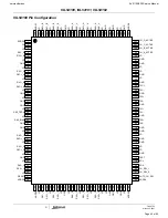
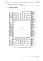
Страница 39: ...52 51 50 49 48 47 46 45 44 43 42 41 80 79 78 77 76 75 74 73 72 71 70 69 68 67 66 65 64 63 62 61 1 2 3 4 5 6 7 8 9 10 11 12 13 14 15 16 17 18 19 20 INT1 BOUT TVDD DVDD DVSS XTO XTI TEST3 MCKO2 MCKO1 CO...

Страница 40: ...harman kardon AVR 155 230 Service Manual Page 40 of 92...

Страница 41: ...CE Chip Enable OE Output Enable WE Write Enable RESET Hardware Reset Pin Active Low BYTE Selects 8 bit or 16 bit mode RY BY Ready Busy Output Vcc 3 0 volt only single power supply see Product Selector...

Страница 42: ...11 DQ3 DQ10 DQ2 DQ9 DQ1 DQ8 DQ0 OE Vss CE A0 1 2 3 4 5 6 7 8 9 10 11 12 13 14 15 16 17 18 19 20 21 22 23 24 48 47 46 45 44 43 42 41 40 39 38 37 36 35 34 33 32 31 30 29 28 27 26 25 48 Pin Standard TSOP...

Страница 43: ...ES DESCRIPTION The HCF4053B is a monolithic integrated circuit fabricated in Metal Oxide Semiconductor technology available in DIP and SOP packages The HCF4053B analog multiplexer demultiplexer is a d...

Страница 44: ...SCRIPTION PIN PIN NAME DESCRIPTION CLK Clock The system clock input All other inputs are referenced to the SDRAM on the rising edge of CLK CKE Clock Enable Controls internal clock signal and when deac...

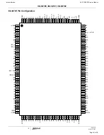
Страница 45: ...IVE CH_SEL_0 RESET PD VD VD CH_C_ACTIVE CH_B_ACTIVE CH_A_ACTIVE CH_SEL_1 TX0 TX0 TX1 GND TX1 TX2 GND TX2 TXC GND TXC ADDR6 RES_BIAS ADDR5 GND GND VD RX0 _A VD RX0 _A RX1 _A RX1 _A RX2 _A VD RX2 _A VD...

Страница 46: ...120 121 122 123 124 125 126 127 128 NC VD NC VD VD GND NC NC RESET PD VD VD NC NC CH_A_ACTIVE NC TX0 TX0 TX1 GND TX1 TX2 GND TX2 TXC GND TXC ADDR6 RES_BIAS ADDR5 GND GND VD RX0 _A VD RX0 _A RX1 _A RX...

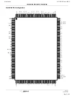
Страница 47: ...127 128 NC VD NC VD VD GND NC CH_SEL_0 RESET PD VD VD NC CH_B_ACTIVE CH_A_ACTIVE NC TX0 TX0 TX1 GND TX1 TX2 GND TX2 TXC GND TXC ADDR6 RES_BIAS ADDR5 GND GND VD RX0 _A VD RX0 _A RX1 _A RX1 _A RX2 _A V...

Страница 48: ...harman kardon AVR 155 230 Service Manual Page 48 of 92...

Страница 49: ...harman kardon AVR 155 230 Service Manual Page 49 of 92...

Страница 50: ...IM MILLIMETERS TO 220IS 4 10 00 0 20 15 00 0 20 2 70 0 20 0 60 0 10 3 20 0 20 3 50 0 10 A B C D E F G 15 70 0 20 0 40 0 10 H 14 3 0 2 0 1 1 45 0 10 1 00 0 10 2 54 4 50 0 20 7 5 0 1 1 50 0 10 J K L M N...

Страница 51: ...harman kardon AVR 155 230 Service Manual Page 51 of 92...

Страница 52: ...harman kardon AVR 155 230 Service Manual Page 52 of 92...

Страница 53: ...harman kardon AVR 155 230 Service Manual Page 53 of 92...

Страница 54: ...Pin Assignment DIP16 MFP16 No 6037 2 8 LC72723 LC72723M Block Diagram harman kardon AVR 155 230 Service Manual Page 54 of 92...

Страница 55: ...tem ground 4 Vssa Crystal element output 4 332 MHz Output 8 XOUT RDS data output Output 14 RDDA RDS clock output master mode RDS clock input slave mode I O 15 RDCL RDS ID ready output Active low Outpu...

Страница 56: ...harman kardon AVR 155 230 Service Manual Page 56 of 92...

Страница 57: ...in the same way Data transfers are terminated by a Stop condition after an Ack for Write and after a NoAck for Read Table 2 Signal Names Power On Reset VCC Lock Out Write Protect In order to prevent d...

Страница 58: ...a Input During data input the device samples Serial Data SDA on the rising edge of Serial Clock SCL For correct device operation Serial Data SDA must be stable during the rising edge of Serial Clock S...

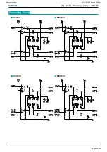
Страница 59: ...MITSUMI Video Switch 75 driver Y C mix MM1501 Measuring Circuit MM1501 MM1502 MM1503 MM1504 harman kardon AVR 155 230 Service Manual Page 59 of 92...

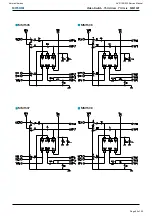
Страница 60: ...MITSUMI Video Switch 75 driver Y C mix MM1501 MM1505 MM1506 MM1507 MM1508 harman kardon AVR 155 230 Service Manual Page 60 of 92...

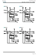
Страница 61: ...MITSUMI Video Switch 75 driver Y C mix MM1501 MM1509 MM1510 MM1511 MM1512 harman kardon AVR 155 230 Service Manual Page 61 of 92...

Страница 62: ...harman kardon AVR 155 230 Service Manual Page 62 of 92...

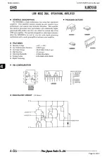
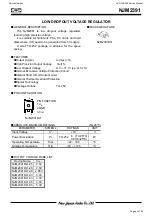
Страница 63: ...1V typ At Io 1A zInternal Excessive Voltage Protection Circuit zInternal Short Circuit Current Limit zInternal Thermal Overload Protection zBipolar Technology zPackage Outline TO 252 PIN CONFIGURATION...

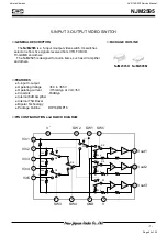
Страница 64: ...K DIAGRAM 13 9 7 5 3 20k 20k 20k 20k 16 10 14 2 1 15 11 8 12 6 4 6dB Amp 75 Driver S3 S2 S4 S1 20k 20k 20k S5 S6 S7 Vin1 Vin2 Vin3 Vin4 Vin5 SW3 SW4 SW5 SW1 SW2 V GND V Vout3 Vout2 Vout1 6dB Amp 6dB A...

Страница 65: ...harman kardon AVR 155 230 Service Manual Page 65 of 92...

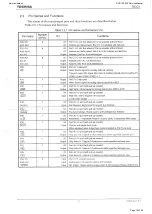
Страница 66: ...capacitor 74 FR Input selector gain control Rch no inverted output 25 R2IN Input selector Rch input 2 75 FR Input selector gain control Rch inverted output 26 DCCAP_RS Switching noise rejection capaci...

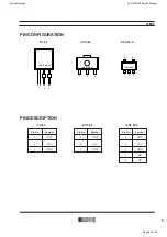
Страница 67: ...IN DESCRIPTION TO 92 SOT 89 SOT 23 5 Pin No Symbol 1 OUT 2 VDD 3 GND 4 NC 5 NC Pin No Symbol 1 OUT 2 VDD 3 GND Pin No Symbol 1 OUT 2 VDD 3 GND 1 2 3 mark side 1 2 3 mark side 1 2 3 mark side 5 4 harma...

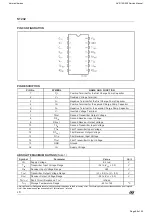
Страница 68: ...r Output Voltage 13 R1IN First Receiver Input Voltage 14 T1OUT First Transmitter Output Voltage 15 GND Ground 16 VCC Supply Voltage ABSOLUTE MAXIMUM RATINGS Note 1 Symbol Parameter Value Unit VCC Supp...

Страница 69: ...harman kardon AVR 155 230 Service Manual Page 69 of 92...

Страница 70: ...harman kardon AVR 155 230 Service Manual Page 70 of 92...

Страница 71: ...harman kardon AVR 155 230 Service Manual Page 71 of 92...

Страница 72: ...harman kardon AVR 155 230 Service Manual Page 72 of 92...

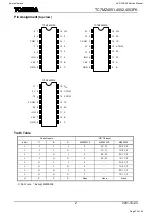
Страница 73: ...5 1X 0Y 1Z L H H L 6 0X 1Y 1Z L H H H 7 1X 1Y 1Z H X X X None None None X Don t care Except MZ4052FK 1 14 0 3 A B C 13 12 11 10 9 15 4 1 2 3 4 5 6 7 6 COM 7 5 INH VEE 2 8 16 GND VCC TC7MZ4051FK 1X 14...

Страница 74: ...harman kardon AVR 155 230 Service Manual Page 74 of 92...

Страница 75: ...harman kardon AVR 155 230 Service Manual Page 75 of 92...

Страница 76: ...harman kardon AVR 155 230 Service Manual Page 76 of 92...

Страница 77: ...harman kardon AVR 155 230 Service Manual Page 77 of 92...

Страница 78: ...harman kardon AVR 155 230 Service Manual Page 78 of 92...

Страница 79: ...harman kardon AVR 155 230 Service Manual Page 79 of 92...

Страница 80: ...harman kardon AVR 155 230 Service Manual Page 80 of 92...

Страница 81: ...harman kardon AVR 155 230 Service Manual Page 81 of 92...

Страница 82: ...harman kardon AVR 155 230 Service Manual Page 82 of 92...

Страница 83: ...AVR155 WIRING sch 1 Wed Mar 12 14 07 28 2008 harman kardon AVR 155 230 Service Manual Page 83 of 92...

Страница 84: ...to CN61 CEN CN64 SR CN63 FL CN65 SBL SL NO 1 2 3 Surround Left Surround Right 4 5 Channel Front Left Front Right Center CN64 25 92mV 5 25 92mV 5 25 92mV 5 25 92mV 5 CN62 CN61 CN65 Adjust for Adjustmen...

Страница 85: ...AVRx54 Front_0119 sch 1 Fri Feb 08 15 10 47 2008 harman kardon AVR 155 230 Service Manual Page 85 of 92...

Страница 86: ...harman kardon AVR 155 230 Service Manual Page 86 of 92...

Страница 87: ...harman kardon AVR 155 230 Service Manual Page 87 of 92...

Страница 88: ...harman kardon AVR 155 230 Service Manual Page 88 of 92...

Страница 89: ...harman kardon AVR 155 230 Service Manual Page 89 of 92...

Страница 90: ...harman kardon AVR 155 230 Service Manual Page 90 of 92...

Страница 91: ...harman kardon AVR 155 230 Service Manual Page 91 of 92...

Страница 92: ...AVR154 VIDEO_20071230 1 sch 1 Fri Feb 08 15 07 04 2008 harman kardon AVR 155 230 Service Manual Page 92 of 92...

Отзывы: