background image


Page 11 of 19 

CUS

-009

-0008

-0

3


5.3  Double deck rotisserie 

5.3.1  Preparation 

1.  Using a crowbar and hammer, remove the top and sides of each packing crate.  


2.  Remove all accessories and loose items from in and around the equipment.  Keep the accessories separate for 

each rotisserie. 


3.  Remove all wrapping from the rotisseries.  Care should be taken not to scratch any surfaces if a knife is being 

used.  Remove all wood blocks around the casters that might hinder the removal from the pallets. 


4.  The bottom rotisserie (the one equipped with caster wheels) must be unpacked and set on the floor first.  


5.  Determine if your rotisserie comes with a wood lifting jig (located inside one of the rotisseries) or the metal lifting 

bracket (installed on the bottom rotisserie).  If using a wood lifting jig then follow the instructions in section 5.3.2, if 
using the metal bracket then follow the instructions in 5.3.3. 

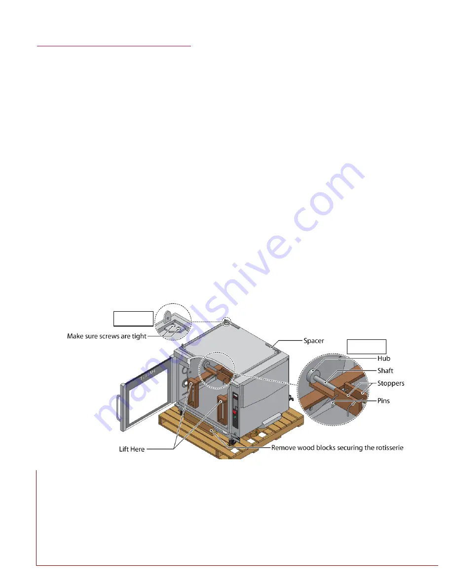
5.3.2  Using the wood lifting jig 

1.  Open the door on the rotisserie. 


2.  Insert the lifting jig inside the cooking cavity, taking care not to damage the door.  The proper orientation is shown 

i

Figure 5-3

. 


3.  Align the jig so the shaft is between the two stoppers built into the jig as shown in detail 2 of 

Figure 5-3

. 


4.  Lift the jig and insert the two pins that hold the jig on the shaft. 


5.  The rotisserie 

may now be lifted by inserting the lift’s forks in the openings of the jig.  The lifting jig should support 

the rotisserie 

from the rotating plates’ hubs and NOT from the shaft as shown in detail 2 of 

Figure 5-3

. 


Figure 5-3: Wood lifting jig in bottom rotisserie (with wheels) 

Detail 1 

Detail 2 

Содержание INFERNO 3500

Страница 1: ...tions Hardt Equipment Manufacturing 1756 50th Avenue Lachine Montreal Quebec Canada H8T 2V5 Technical Support Tel 800 387 6847 514 631 7271 Fax 514 631 5443 Sales Tel 888 848 4408 www hardtequipment com HARDT Document No CUS 009 0008 03 This manual is to be left to the customer for future references ...

Страница 2: ...lteration service or maintenance can cause property damage injury or death Read the installation operating and maintenance instructions thoroughly before installing or servicing this equipment IMPORTANT You must post in a prominent location instructions to be followed in the event the user smells gas Specific instructions can be obtained from your local gas supplier IMPORTANT DO NOT HINDER THE EFF...

Страница 3: ...2 Single rotisserie 10 5 3 Double deck rotisserie 11 5 3 1 Preparation 11 5 3 2 Using the wood lifting jig 11 5 3 3 Using the metal lifting bracket 12 5 3 4 Finishing up 13 6 Installing the equipment 14 6 1 Venting 14 6 1 1 Hood specification recommendations 14 6 2 Drain 15 6 2 1 Plumbing the 1 5 3 8 cm overflow line 15 6 2 2 Plumbing the 1 2 5 cm auto clean drain line 15 6 3 Electrical 15 6 4 Gas...

Страница 4: ... by a licensed plumber All electrical connection installation must be done by a qualified electrician The strain relief cable must be installed by a qualified contractor ENSURE THAT ELECTRICAL CORDS ARE UNDAMAGED AND NO BARE WIRES ARE VISIBLE ENSURE THAT THERE ARE NO WATER LEAKS FROM THE ROTISSERIE FAILURE TO DO SO CAN RESULT IN INJURY OR PROPERTY DAMAGE DO NOT STORE OR USE GASOLINE OR OTHER FLAMM...

Страница 5: ...meter 3 3 Warranty information Please note that failure to follow these instructions can result in damage to your equipment that is not covered under warranty Any damage or costs incurred due to any of the following situations will not be covered Unauthorized repair by anyone other than a HARDT factory authorized service partner Installation of non Hardt replacement or service components Alteratio...

Страница 6: ...ams 4 1 Single rotisserie Auto Clean Drain 1 Electrical Cord Water Inlet Gas Inlet Power Switch Halogen Lamp Access Panel Overflow 1 5 Control Panel Manual Drain Valve Chimney Degreaser Shelf Flame Detector Access Panel Figure 4 1 Single Rotisserie ...

Страница 7: ...p vent rotisserie Overflow 1 5 Control Panel Manual Drain Valve Vent Degreaser Shelf Halogen Lamp Access Panel Gas Inlet Power Switch Water Inlet Auto Clean Drain 1 Electrical Cord Figure 4 2 Single Top Vent Rotisserie Flame Sensor Access Panel ...

Страница 8: ...mp Access Panel Manual Drain Valves Overflow 1 5 Control Panels Degreaser Shelf Chimneys Chimney Bracket Machine Room Ventilation Elbow Figure 4 3 Double Deck Rotisserie Flame Detector Access Panel Auto Clean Drain 1 Electrical Cord Water Inlet Gas Inlet Power Switch ...

Страница 9: ...WAYS LEVEL OTHERWISE THE BALANCE MIGHT BE UPSET RISKING DAMAGE OR INJURY CONTACT OF THE FORK LIFT WITH ANY PART OF THE ROTISSERIE OTHER THAN THE LIFTING JIG WILL RESULT IN DAMAGE TO THE ROTISSERIE 5 1 Unpacking Verify that all required components have been shipped with your rotisserie s by referring to the table below Equipment configuration Included components Single rotisserie Chimney Stack rear...

Страница 10: ... in Figure 5 1 7 Lift the jig and insert the two pins that hold the jig on the shaft 8 The rotisserie may now be lifted by inserting the forklift forks in the openings of the jig The lifting jig should support the rotisserie from the rotating plates hubs and NOT from the shaft as shown in detail 1 of Figure 5 1 9 Lift the rotisserie off its pallet and set it on the floor 10 Remove the lifting jig ...

Страница 11: ...r the metal lifting bracket installed on the bottom rotisserie If using a wood lifting jig then follow the instructions in section 5 3 2 if using the metal bracket then follow the instructions in 5 3 3 5 3 2 Using the wood lifting jig 1 Open the door on the rotisserie 2 Insert the lifting jig inside the cooking cavity taking care not to damage the door The proper orientation is shown in Figure 5 3...

Страница 12: ... wheels 2 Ensure the screws at each corner of the lifting bracket are tight see detail of Figure 5 5 3 Insert the forklift s forks under the metal lift bracket as shown in Figure 5 5 4 The bottom rotisserie may be lifted from the pallet Figure 5 4 Metal lifting bracket on top rotisserie without wheels Figure 5 5 Metal lifting bracket on bottom rotisserie with wheels ...

Страница 13: ...or details 5 Place the top rotisserie on to the bottom one The four tabs on the spacer must be inserted inside the frame of the top rotisserie The holes in the base of the top rotisserie must align with the holes in the tabs on the spacer of the bottom rotisserie 6 Insert bolts and tighten As shown in Figure 5 6 7 Remove the wood lifting jig or metal lifting bracket from the top rotisserie Be care...

Страница 14: ...event the rotisserie from being moved for cleaning The screws required for mounting the chimneys should already be located in the vents to which the chimneys will be connected Double deck rotisseries Install the upper and lower chimneys onto the rotisserie as shown in Figure 6 2 Ensure both chimneys are held in place by the support bracket Install the machine room ventilation elbow as shown in Fig...

Страница 15: ...separation system may plumb the unit directly into this drain Locations without a grease separation unit must collect the effluent into containers and transferred to a rendering barrel for proper disposal The overflow pipe on each rotisserie must be screwed into place and secured with a U bolt as shown in Figure 6 3 6 2 2 Plumbing the 1 2 5 cm auto clean drain line The 1 2 5 cm drain line is locat...

Страница 16: ... BE INSTALLED SUCH THAT THE ROTISSERIE MOVEMENT IS LIMITED WITHOUT RELYING ON THE QUICK DISCONNECT HARDWARE OR ITS ASSOCIATED PIPING IT IS REQUIRED THAT INFERNO 3500 ROTISSERIES BE EQUIPPED WITH QUICK DISCONNECT GAS WATER INSTALLATION HARDWARE 6 4 1 Gas pressure Natural Gas Incoming Pressure 7 W C 1 74 kPa 12 W C 2 99 kPa Propane Incoming Pressure 11 W C 2 74 kPa 12 W C 2 99 kPa 6 4 2 Quick discon...

Страница 17: ...ply an approved thread sealant to the threaded pipe end on the gas pipe extending from the rear of the rotisserie 4 Screw the quick disconnect fitting pipe adapter shown in Figure 6 4 onto the threaded connection 5 Attach the flexible gas supply hose to the facility gas supply line and connect the gas to the rotisserie by sliding the quick disconnect hose fitting onto the pipe adapter 6 Open the m...

Страница 18: ...oftener directly on the rotisserie 6 5 2 Water connection 1 Ensure the facility water supply is turned off 2 Locate the water inlet connection at the lower rear right corner of the rotisserie see Figure 6 6 3 Apply Teflon thread sealant to the NPT fitting and screw on the threaded quick disconnect fitting purchased with the rotisserie 4 Apply Teflon thread sealant to the large diameter of both mal...

Страница 19: ...ings closed or farther open then additional leveling is required If a rotisserie is not level the caster wheel height can be adjusted as described on page 10 for single deck units and on page 11 for double deck units Is each rotisserie connected to a hot water source If not please connect the water inlet to a hot water source Does the minimum incoming gas pressure conform to the rotisserie s requi...

Отзывы: