Hardi NL Series Скачать руководство пользователя страница 6

4

We congratulate you for choosing a HARDI plant protection product.
The reliability and efficiency of this product depend on your care. The
first step is to carefully  read and pay attention to this instruction
book. It contains essential information for the efficient use and long life
of this quality product.

As the instruction book covers all NL models, please pay attention to
the paragraphs dealing with precisely your model. This book is to be
read in conjunction with the Spray Technique book.

Description

The Hardi NL models consist of a pump, frame with tank of 300, 400,
600 or 800 litre capacity, M-70 operating unit, SB booms (if fitted) of 6,
8, 10, or 12 metre  and transmission shaft.

The design of the diaphragm pump is simple, with easily accessible
diaphragms and valves that ensures liquid does not come in contact
with the vital parts of the pump.

The tank, made of impact-proof and chemical resistant polyethylene,
has a purposeful design with no sharp edges for easy cleaning and
efficient agitation. A suction filter is located at the top of the tank. This
facilitates filter inspection even if the tank is filled with spray liquid.

The M-70 operating unit consists of; on/off function, pressure regula-
tion valve with pressure gauge and distribution valves for closing of
spray boom sections.

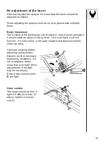
The SB boom is bolted to the tank frame and is fitted with spring
loaded breakaways at the pivots.

An identification plate fitted on the frame indicates model, year of
production and serial number, and country of origin.

Содержание NL Series

Страница 1: ...NL Instruction book 674202 GB 10 1995 www hardi international com ...

Страница 2: ...omplete and correct As this instruction book covers more models and features or equipment which are available in certain countries only please pay attention to paragraphs dealing with precisely your model Published and printed by HARDI INTERNATIONAL A S We congratulate you for choosing a HARDI plant protection product The reliabi lity and efficiency of this product depend upon your care The first ...

Страница 3: ...yer 5 Transmission shaft 6 Rear lights if fitted 7 Roadworthyness 7 Operating instructions 8 Filling the main tank 8 Operation of the boom 8 Boom height 9 Pulsation damper 9 Adjustment of the operating unit 10 Drain valve operation 11 Maintenance 11 Filters 11 Lubrication 12 Re adjustment of the boom 15 Changing of valves and diaphragms 16 Nozzle tubes and fittings 18 Off season storage 18 Operati...

Страница 4: ...ation of the laws of the Member States on the safety of machines 89 392 EEC as amended by directives 91 368 EEC and 93 368 EEC with special reference to Annex 1 of the Directive on essential safety and health requirements in relation to the construction and manufacture of machines B was manufactured in conformity with the standards current at that time that implements a harmonised standard in acco...

Страница 5: ...ng Never service or repair the equipment whilst it is operating Disconnect electrical power before servicing Always replace all safety devices or shields immediately after servicing If an arc welder is used on the equipment or anything connected to the equipment disconnect power leads before welding Re move all inflammable or explosive material from the area Do not eat drink or smoke whilst sprayi...

Страница 6: ... metre and transmission shaft The design of the diaphragm pump is simple with easily accessible diaphragms and valves that ensures liquid does not come in contact with the vital parts of the pump The tank made of impact proof and chemical resistant polyethylene has a purposeful design with no sharp edges for easy cleaning and efficient agitation A suction filter is located at the top of the tank T...

Страница 7: ...I 28 mm category II pivots are fitted on the 800 litre models WARNING Note the weight of the sprayer See section on Technical specifications Generally it is recommended to 1 Add ballast to front of tractor 2 Increase tyre pressure see tractor instruc tion book 3 Travel at slower speeds when driving with a full tank The tractor will have decreased braking efficiency 4 Be careful when filling liftin...

Страница 8: ...tion guard Do not touch or stand on the transmission shaft when it is rotating safety distance 1 5 meter Prevent protection guards from rotating by attaching the chains allowing sufficient slack for turns Make sure that protection guards around tractor P T O and implement shaft are intact Always STOP ENGINE and remove the ignition key before carrying out maintenance or repairs to the transmission ...

Страница 9: ...long life of the transmission shaft try to avoid working angles larger than 15 8 Transmission shafts with cone must be fitted by tightening the Allen screw to a torque of 40 Nm Check again Rear lights if fitted Connect plug for rear lights to tractors 7 poled socket and check that rear lights stop lights and turning indicators function properly Roadworthyness When driving on public roads and other...

Страница 10: ...e filling hose enter the tank Keep it outside the tank pointing towards the filling hole If the hose is lead into the tank and the water pressure drops at the water supply plant chemicals may be syphoned back and contaminate the water supply lines plant and well Operation of the boom Remove boom transport lock pin When unfolding or folding the initial force to release the spring loaded breakaways ...

Страница 11: ...ter adjustments are needed the boom height can be changed manually by removing the 4 bolts holding the boom to the frame Note This is best done by 2 persons or with a mechanical hoist Pulsation damper The air pressure in the pulsation damper is preset at the factory to 2 bar This covers spray working pressures between 3 and 15 bar When using spray pressures outside this range the air pres sure sho...

Страница 12: ...e 1 to spraying position B 5 Now turn the pressure regulating valve 3 to until the required pres sure is indicated on the pressure gauge 6 Operating the control unit while driving To close the entire boom turn the handle 1 to position A This takes the pressure off the pump The liquid will then return to the tank via the return system The diaphragm anti drip valves ensure instantaneous closing of a...

Страница 13: ...e Sprayer components such as valves diaphragms and operating unit are not hindered or damaged during opera tion Nozzle blockages do not occur whilst spraying Long life of pump A blocked suction filter will result in pump cavitation The main filter protecting sprayer components is the suction filter at the top of the tank Check it regularly Ensure the O ring on filter housing is in good condition a...

Страница 14: ...ase lithium grease No 2 NOTE If the sprayers are cleaned with a high pressure cleaner or it has been used to spray fertilizer we recommend lubrication of the entire machine 5 5 Position on sprayer Oil Grease Operation hours Page to find more information Winter protection off season storage ...

Страница 15: ...13 1 X 40 2 A X 12 B X 40 3 X 20 16 17 17 6 10 19 ...

Страница 16: ...14 4 X 40 5 X 40 15 15 ...

Страница 17: ...ke an object or the ground If it is over tight it will not function If it is too loose it will yawn forward and back movement under spraying Lubricate coupling before adjusting spring tension Slacken nut A to decrease breakaway resistance Do not overtighten better loose than over tight Minor adjustments in the field may be necessary Ensure also channel bolts B are tight Outer section The hinge sho...

Страница 18: ... correctly It is recommended to use new gaskets 3 when changing or checking the valves Diaphragms Remove the diaphragm cover 4 after having dismantled the valve cover The diaphragm 5 may then be changed If fluids have reached the crankcase re grease the pump thoroughly Check also the drain hole at the bottom of the pump is not blocked Model 1202 Model 600 ...

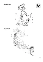
Страница 19: ...17 Model 1302 Model 320 ...

Страница 20: ...ions only hand tighten them The O ring to be lubricated ALL THE WAY ROUND before fitting on to the nozzle tube For axial connections a little mechanical leverage may be used Off season storage When the spraying season is over you should devote some extra time to the sprayer before it is put away for the winter Hoses Check that none of the hoses are caught or have sharp bends A leaky hose can give ...

Страница 21: ...eby relieved and operation difficul ties are avoided at start up next season Transmission shaft Check that the transmission shaft fulfills its security purpose e g that shields and protective tubes are intact Anti freeze precaution If the sprayer is not stored in a frost proof place you should take the following precautions Put at least 10 litres of 33 anti freeze mixture in the tank and let the p...

Страница 22: ...wer pressure at the nozzles Foreign bodies stuck in the pump valves with the result that these cannot close tightly against the valve seat This reduces pump efficiency Poorly reassembled pumps especially diaphragm covers will allow the pump to suck air resulting in reduced or no capacity Therefore ALWAYS check 1 Suction and nozzle filters are clean 2 Hoses for leaks and cracks paying particular at...

Страница 23: ...l suction hose with water for initial prime Clean filters Check yellow suction pipe is not obstructed or placed too near the tank bottom Check for obstructions and wear Check for dirt at inlet of gauge Clean all filters Fill with cleaner water Check flow rate and replace nozzles if it exceeds 10 Check vent is clear Clean all filters Check tightness gaskets O rings of all fittings on suction side R...

Страница 24: ...2 1302 140 x 256 x 260 209 800 10 1302 140 x 190 x 210 223 12 1302 140 x 256 x 260 235 Pump Measure Weight model a x b x c cm kg 600 70 x 83 x 120 99 320 70 x 83 x 120 107 600 70 x 98 x 132 106 1202 70 x 98 x 132 115 320 70 x 98 x 132 114 600 77 x 119 x 139 123 1202 77 x 119 x 139 131 1302 77 x 119 x 139 142 320 77 x 119 x 139 132 1302 77 x 160 x 143 163 Tank Boom height A B C D E size l Min H mm ...

Страница 25: ...Max pressure 15bar Weight 35 0 kg r min 300 400 500 540 600 bar l min kW l min kW l min kW l min kW l min kW 0 56 0 91 72 1 28 93 1 52 99 1 63 112 1 79 5 40 1 11 53 1 36 66 1 60 71 1 71 79 1 86 10 38 1 38 52 1 74 64 1 79 69 1 87 77 2 07 15 37 1 60 50 1 97 62 2 32 67 2 48 75 2 76 Rotation per min r min Capacity l min Suction height 0 0 m Power consumption kW Max pressure 15bar Weight 24 0 kg 1202 9...

Страница 26: ...our nozzle 1 30 Suction filter 2 50 blue Nozzle 4110 20 2 1 Pictorial symbols Description Function Connection Warning Operating Service adjustment Liquid flow Pressure Cleaning Lubrication Winter storage Operational problems Technical specifications ...

Страница 27: ...re assembly Some components are shipped within the tank Check inside To verify connection of hoses a function diagram is included on page 32 Packaging information Materials used for packaging are environmentally compatible They can be safely deposited or they can be burnt in an incinerator Recycling Cardboard Can recycle up to 99 and therefore should be put into the waste collection system Polysty...

Страница 28: ... O rings where indicated Lubricate them before assembly Where O rings are not indicated use sealing tape 1 Fit pulsation damper and pressure hose B 2 Fit suction damper and suction hose A 3 Fit bottom half of yellow protective guard Remember washer ...

Страница 29: ...it hoses Remember to lubricate O rings before fitting B From pump C Return to tank F Feed hoses to boom For 12 metre boom shortest hose is for centre section G From on off unit to distribution valves 4 5 4 Bolt pump to console Position pulsation damper so it fits into cavity 5 Lubricate conical shaft lightly and connect transmission shaft Attach chain to prevent rotation of the protective guard Re...

Страница 30: ... before fitting A Suction hose to pump C Return to tank NOTE For sake of good order it may be necessary to shorten some hoses for example suction hose A This is best done when assembly is completed and before hoses are secured with plastic straps ...

Страница 31: ...15 12 Tighten black metal tank straps if loose 13 Bolt angle brackets to frame 14 Fit boom centre 15 Fit U profile 16 Fit boom wings Be cautious when folding boom for the first time See section on Boom breakaway 800 l ...

Страница 32: ... 12 metre booms fit outer section springs Note orientation of spring anchor 18 Nozzle tubes are supplied with one lock nozzle saddle per tube A The rest can slide lengthwise B allowing for extension and contraction B A ...

Страница 33: ...31 19 Tubes and hoses are connected Fit tubes using synthetic nut Press down 1 turn 2 Do not over tighten Fit filter and nozzle REMEMBER Lubricate O rings before fitting ...

Страница 34: ...32 G C B A F 21 Verify connections with diagram 20 Fit boom transport lock Arrow indicates forward direction of travel ...

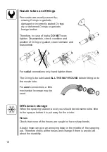
Страница 35: ...33 22 Organise hoses it may be necessary to shorten some of them Secure with straps ...

Страница 36: ...34 A6 600 foot ...

Страница 37: ...35 320 A8 ...

Страница 38: ...36 A10 1202 foot ...

Страница 39: ...37 1303 foot A12 ...

Страница 40: ...38 B5 Unit M 70 70 HT ...

Страница 41: ...39 Distributor B6 ...

Страница 42: ...40 B300 Damper HJ73 ...

Страница 43: ...41 SB 6 8 10 m D3 ...

Страница 44: ...42 D5 SB 12 m ...

Страница 45: ...43 Boom tube 3 8 cap D901 ...

Страница 46: ...44 E3 NK 300 400 ...

Страница 47: ...45 NL NK 300 400 E102 ...

Страница 48: ...46 E103 NL NK 600 800 ...

Страница 49: ...47 Shaft 94 K604 HARDI INTERNATIONAL A S HELGESHØJ ALLÉ 38 DK 2630 TAASTRUP DENMARK HARDI 0396 EN 1152 ISO 5674 978389 rpm kW Nm 540 12 210 1000 18 172 POS A X 8 B X 40 ...

Страница 50: ...48 Notes ...

Страница 51: ...Spare parts To see updated spare part information the website www agroparts com can be visited Here all parts information can be accessed when free registration has been made ...

Страница 52: ...HARDI INTERNATIONAL A S Herthadalvej 10 DK 4840 Nørre Alslev DENMARK ...

Отзывы: