background image

6 - Maintenance

88

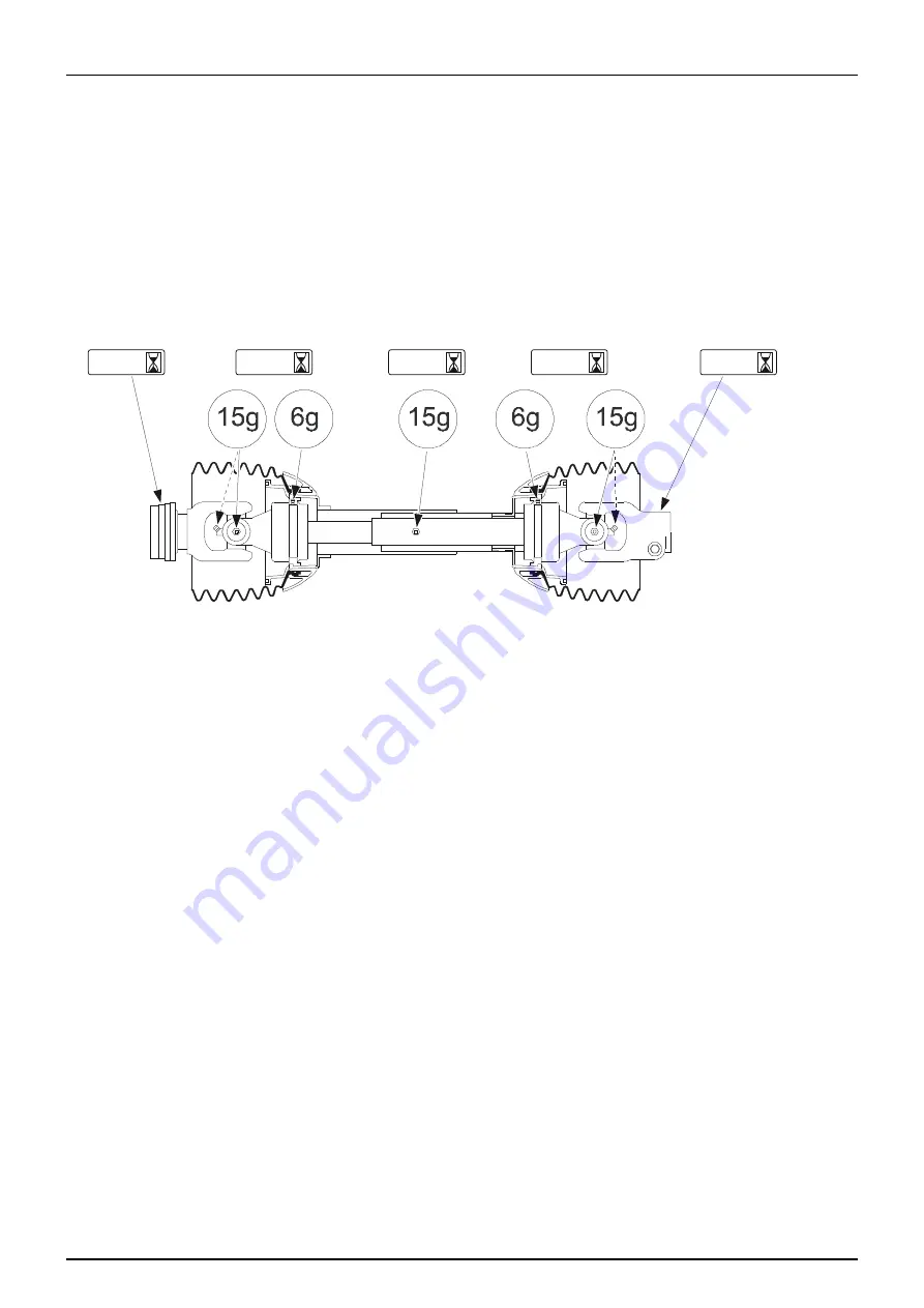
Lubrication & Oiling Plan - PTO 

The amount of grease to be applied is mentioned in grams (g). Test your grease gun to see how many grams it provides, for 
example after 5 strokes.

μ

ATTENTION! The correct amount of grease applied at the intervals is important. Too little or too much grease will 
shorten the lifetime of the PTO.

The grease points and amount of grease to be applied are shown in the pictures below together with the intervals.

Standard PTO for tractor and sprayer

A-50

A-50

B-50

C-50

C-50

Tractor

Sprayer

Содержание NK SB Series

Страница 1: ...NK SB MB Original Instruction book 67007200 110 version 1 10 GB 12 2015 www hardi international com...

Страница 2: ...ducts we reserve the right to make changes in design features accessories specifications and maintenance instructions at any time and without notice HARDI INTERNATIONAL A S is without any obligation i...

Страница 3: ...9 Operator Training 20 Authorized Persons 20 Safety Measures in Normal Operation 21 Protection Equipment 21 Residual Energy 22 Possible Dangers 22 Service and Maintenance Work 23 Statutory Inspection...

Страница 4: ...1 External Cleaning Device 51 4 Sprayer Setup General Info 53 Unloading the Sprayer from the Truck 53 Before Putting the Sprayer into Operation 53 Checking the Suitability of the Tractor 54 General In...

Страница 5: ...ck Reference Cleaning 77 Standard Cleaning 78 Cleaning the Tank and Liquid System 79 Cleaning and Maintenance of Filters 79 Use of Detergents 79 Use of Rinsing Tank and Rinsing Nozzles Optional 80 Ful...

Страница 6: ...101 General Info 101 Before Storage 101 After Storage 102 7 Fault Finding Operational Problems 103 General Info 103 Liquid System 104 Hydraulic System 105 Mechanical Problems 106 Emergency Operation...

Страница 7: ...lev DENMARK Telephone 45 4358 8500 Internet www hardi international com Spare Parts To see or updated spare parts catalogue visit the Agroparts website on the internet Here all spare parts information...

Страница 8: ...1 Identification 8...

Страница 9: ...dingit please contact the manufacturer or your HARDI dealer A worker is hereinafter called an operator An operator is a person who installs operates configures adjusts maintains cleans repairs transpo...

Страница 10: ...uipment has been installed correctly and is operating properly 2 In order to ensure that health and safety conditions are maintained and that deterioration liable to result in dangerous situations can...

Страница 11: ...them inasmuch as they affect work equipment situated in their immediate work area or site even if they do not use such equipment directly 3 The information and the written instructions shall be compre...

Страница 12: ...ial by authorized persons The results of inspection testing shall be recorded and kept Health Issues Ergonomics and occupational health aspects shall be taken fully into account by the owner Obligatio...

Страница 13: ...ollowing causes Improper use of the sprayer Improper installation commissioning operation and maintenance of the sprayer Operation of the sprayer with defective safety equipment or improperly attached...

Страница 14: ...rovided by the manufacturer of the plant protection product to be used such as This Instruction Book must always be kept together with the sprayer must always be easily accessible for the operator Che...

Страница 15: ...r serious physical injury if the instruction is not followed This symbol means WARNING Be alert as your safety can be involved The WARNING symbol indicates a medium risk for immediate death or serious...

Страница 16: ...mations about chemical preparation before handling the machine Observe instructions and safety rules when operating Service Carefully read the Instruction Book before handling the machine Observe inst...

Страница 17: ...isk of falling off Do not ride on platform or ladder Risk of sprayer tipping over Be aware when disconnecting the sprayer Grapping area Manual handling of the boom etc Not for drinking This water must...

Страница 18: ...er is started up all the safety and protection equipment must be properly attached and fully functional Check all safety and protection equipment regularly Repair or replace the equipment as needed Fa...

Страница 19: ...The applicable workplace safety Follow these regulations especially when driving on public roads and routes Comply with the appropriate statutory road traffic regulations These vary from country to co...

Страница 20: ...cal training shall be considered as a specialist Due to their specialist training and their knowledge of the appropriate regulations they can evaluate the work with which they have been appointed to a...

Страница 21: ...in Normal Operation Protection Equipment Only operate the sprayer if all the safety and protection equipment is fully functional Check the sprayer at least once a day for visible damage and check the...

Страница 22: ...ts from happening due to residual energy Below are some examples on where the sprayer s residual energies may be present Mechanical Energy springs under tension weights exposed to gravity Hydraulic En...

Страница 23: ...actor s hydraulic levers in neutral position to relieve oil pressure turn off the tractor and remove the ignition key dismount the hydraulic hoses connected from the tractor to the sprayer Electric sy...

Страница 24: ...the state specified by the approval It is strictly forbidden to drill holes in the steel frame or in the running gear increasethesize of existing holes in the steel frameor inthe runninggear weld supp...

Страница 25: ...Instructions 25 Cleaning and Disposal Environmental Protection Carefully handle and dispose of any materials used in particular when carrying out work on oiled or lubricated sprayer parts when cleanin...

Страница 26: ...feres with the operator or if the operator is trying to operate the sprayer from other places than the tractor s driver seat this can result in negligent or incorrect handling of the vehicle risk of t...

Страница 27: ...to people to the environment and to the sprayer danger to people through non secured working areas danger to people through mechanical and chemical influences failure of important sprayer functions fa...

Страница 28: ...forbidden to stay in the working area of the sprayer s drawbar on the sprayer s platform or behind the operating area the tractor unless the hydraulic pressure to the sprayer has been switched off On...

Страница 29: ...led sprayers are stable Use of The Sprayer Before starting work ensure that you understand all the equipment and actuation elements of the sprayer and their function There is no time for this when the...

Страница 30: ...t be strained or caught in the tractors wheels when cornering 14 Crop residues and dirt are removed 15 All moveable or loose equipment are securely latched or stowed away in the designated compartment...

Страница 31: ...ition or into the transport position turn off depressurize the hydraulic system turn off the tractor engine engage the parking brake remove the ignition key Havethehydraulichose linescheckedatleastonc...

Страница 32: ...lectric components Only use the prescribed fuses If the fuses used are too highly rated the electrical system will be destroyed Risk of fire Thesprayermaybe equippedwith electroniccomponents whosefunc...

Страница 33: ...efore switching on the universal joint shaft check that the selected universaljoint shaft speed rpm of the tractor matches the permitted drive speed of the sprayer Stay below the maximum speed rpm sui...

Страница 34: ...ng a free flow of water from the mains water supply or from an external water tank Environmental Precautions It is essential to reduce the environmental impact of plant protection chemicals to a minim...

Страница 35: ...rayer to prevent unintentional movements of the sprayer switch off the PTO switch off the tractor and remove the ignition key to prevent unintentional starting activate the parking brake to prevent ro...

Страница 36: ...eating and retighten them as necessary If electrical welding is used on the tractor and on the attached sprayer disconnect the cable to the tractor s generator and battery before carrying out electric...

Страница 37: ...Self Cleaning Filter for EVC operating unit 4 Rinsing Tank 5 External Cleaning Device ON OFF 6 Spray Section Valves A EVC operating unit B BK operating unit 7 Spray Pressure Gauge 8 Drain Valve Handl...

Страница 38: ...Rear View ATTENTION The sprayer is equipped with optional equipment 17 Main Tank 18 Rinse Tank 19 Hose Reel for External Cleaning Device 20 Road Lights 21 ChemFiller 22 Clean Water Tank 23 Spray Boom...

Страница 39: ...used Reserved for future use 5 Type Defined type related to type approvals definition A grouping based on shared characteristics E g lift sprayer trailer sprayer mist blower field sprayer self propell...

Страница 40: ...t proof polyethylene resistant to UV radiation and chemicals The main tank has a purposeful design with no sharp corners for easy cleaning The filling hole is placed in the centre of the sprayer An op...

Страница 41: ...enabling the ChemFiller functions ChemFiller Functions B Point handle up or down to empty the ChemFiller Valve is closed when handle is in horizontal position C The flip valve engages the ChemFiller f...

Страница 42: ...filters to ensure proper functions and to protect the interior of the pump Self Cleaning Filter With the self cleaning filter the impurities that exist in the spray liquid will be filtered out and ret...

Страница 43: ...lve safety valve main ON OFF valve pressure filter with pressure gauge distribution valves with pressure equalization and HARDI MATIC pressure control valve EVC Control Unit The system is based on EVC...

Страница 44: ...e pump or is used for agitation in the tank If the valve is kept closed the liquid will be directed back to the main tank When the tank is nearly empty the handle is turned to pump so that the liquid...

Страница 45: ...Distribution Valves 10 Pressure Gauge 12 Spray Boom 13 Agitation Valve 14 Agitation Nozzles 15 Return Line for Main Tank 46 Pressure Regulation 48 External Filling Device Valve Optional 52 Return Lin...

Страница 46: ...r 9 Distribution Valves 10 Pressure Gauge 12 Spray Boom 13 Agitation Valve 14 Agitation Nozzles 15 Return Line for Main Tank 17 Safety Valve 46 Pressure Regulation 48 External Filling Device Valve Opt...

Страница 47: ...les 15 Return Line for Main Tank 19 Rinsing Nozzle 20 Rinse Tank 33 External Cleaning Valve and Spray Gun 46 Pressure Regulation 48 External Filling Device Valve 52 Return Line Pressure Equalization 5...

Страница 48: ...Return Line for Main Tank 17 Safety Valve 19 Rinsing Nozzle 20 Rinse Tank 33 External Cleaning Valve and Spray Gun 46 Pressure Regulation 48 External Filling Device Valve 52 Return Line Pressure Equal...

Страница 49: ...the boom against vibrations and shocks when driving on uneven ground This ensures longer boom life and improves boom stability for better spray distribution Height adjustment of the boom can be manual...

Страница 50: ...red at the nozzle Both when calibrating and spraying the pressure must be adjusted according to the readings of this pressure gauge Safety Locker A safety locker A can be mounted on the sprayers left...

Страница 51: ...vice This equipment comprises a hose reel and a spray gun A for cleaning the complete sprayer externally in the field with clean water The External Cleaning Device is located on the boom centre sectio...

Страница 52: ...3 Description 52...

Страница 53: ...nks are empty Before Putting the Sprayer into Operation Although the sprayer has been supplied with a strong and protective surface treatment on steel parts bolts etc in the factory it is recommended...

Страница 54: ...bility of a tractor are in particular Permissible total weight Permissible approved axle loads Load capacity of the tyres fitted Approved front weights must be sufficient You can find this data on the...

Страница 55: ...ee tractor s instruction book or documentation or data for front weights or perform a measurement A1 m Distance from the centre of the front axle to the centre of the lower link connection See tractor...

Страница 56: ...NGER It is forbidden to couple the sprayer to the tractor if one of the actual calculated values is greater than the permissible value or if there is no front ballast if required mounted on the tracto...

Страница 57: ...r Also NEVER cross over a rotating PTO shaft to reach the other side of the sprayer 7 Prevent protection guards from rotating by attaching the chains allowing sufficient slack for turns 8 Make sure th...

Страница 58: ...f the hydraulic system Due to high pressure hydraulic oil may penetrate the skin Requirements for Tractor The hydraulic system requires One single acting outlet for raise and lower of the boom One dou...

Страница 59: ...hidden behind front corner cover Check the tractor s instruction book for information regarding attachment points Three mounting tubes B are supplied One two or all three may be used They can be bent...

Страница 60: ...cordance with ISO 1724 See the section Technical Specifications ATTENTION Turn OFF all work lights when driving on public roads Power Supply Power requirement is 12 V DC Always note polarity For prope...

Страница 61: ...restrictor Start witha black one then a white and finally a red one When cleaning the filter remove the hose N and the hose at the safety valve and check that there are no residues Standard filter si...

Страница 62: ...4 Sprayer Setup 62...

Страница 63: ...5 Operation General Info Environmental Info For environmental info please refer to the following parts in the Spray Technique Book Nozzles Spray quality Choosing nozzles for arable crops Spraying spe...

Страница 64: ...en folding or unfolding the boom make sure that no persons or objects are within the operating area of the boom DANGER Always follow the guidelines listed below when driving in areas with overhead pow...

Страница 65: ...he boom wing up and outwards until it clicks into locked position A 5 Unlock the trapeze suspension by removing the lock pin B The lock pin can be stored at the hole farther to the left C ATTENTION On...

Страница 66: ...n must be no closer than 1 50 metres from public water supplies for drinking purposes and 2 25 metres from non public water supplies for drinking purposes and from treatment sumps and cesspools of dra...

Страница 67: ...by overfilling Follow local legislation in force at any time Filling of Rinsing Tank Optional The rinsing tank is fitted to the sprayers right side and is filled via the lid A on the top of the tank 1...

Страница 68: ...ce to discontinue filling process Now disengage the pump Disconnect suction hose and replace cover DANGER Prevent contamination or injury Do not open suction valve towards Filling Device unless the pu...

Страница 69: ...emical resistance WARNING Protective clothing equipment should be used when preparing the spray liquid during the spray job and when cleaning the sprayer Follow the chemical manufacturer s instruction...

Страница 70: ...osition Failure to do so causes a risk of contamination and injury from the quick coupler lid being shot off when pressurized If it is not possible to mount the lid completely lubricate the rubber sea...

Страница 71: ...r concentrated chemicals Before disposal always rinse thechemicalcontainerswith clean water severaltimes until they are clean 7 Flush the ChemFiller with clean water from the rinsing tank by shifting...

Страница 72: ...DANGER Always wear face shield and other appropriate personal safety equipment when filling chemicals 6 If the chemical container is empty it can be rinsed by the Chemical Container Cleaning device P...

Страница 73: ...ion and turn the agitation valve towards Agitation If BK operating unit turn agitation on at lever on BK operating unit Other valves are closed 2 Engage the pump and set PTO speed to 540 rpm 3 Agitati...

Страница 74: ...is emptied out of the ChemFiller ChemFiller rinsing ChemFiller lid is closed 1 Close ChemFiller lid 2 Turn the suction valve towards Rinsing tank 3 Open the ChemFiller Suction valve A and then open th...

Страница 75: ...ilizers ATTENTION Pressure values below 1 5 bar or above 5 0 bar are considered to be out of range for the nozzles NOTE Find the density for your liquid fertilizer on the packaging or on the material...

Страница 76: ...s ditches wells springs etc The washings from the cleaning area must not enter sewers Alternatively the washings can be retained in an appropriate receptacle diluted and distributed over a larger cult...

Страница 77: ...on valve On and turn ChemFiller flush valve On B Turn On C Turn Off D Minimum 45 seconds with nozzles OFF E Spray until air comes out of nozzles When the boom is completely empty close the main ON OFF...

Страница 78: ...alve completely 3 Turn suction valve towards and the pressure valve towards with all sections off for approximately 45 seconds 4 Turn all sections on Spray until air comes out of nozzles When the boom...

Страница 79: ...s work best if they are left in the tank for a short period Check the label 5 Drain the tank and let the pump run dry Rinse inside of the tank again letting the pump run dry 6 Stop the pump If the pes...

Страница 80: ...rip to clean this device D Open the ChemFiller lid again and make sure that the ChemFiller is empty E When empty close the ChemFiller suction valve again 6 Turn the suction valve towards and the press...

Страница 81: ...ayer is cleaned with a high pressure washer lubrication of the entire machine is recommended Full Internal Cleaning Soak Wash ATTENTION This cleaning procedure is always used if one or more of these s...

Страница 82: ...e ChemFiller in step 8 and 9 Operate all 4 valves during this process 20 Dismantle all filters suction pressure in line and nozzle filters and clean the filter screens using clean water and detergent...

Страница 83: ...wash everything on the outside of the sprayer 1 Remove split A to turn out hose reel B 2 Unroll the hose from the reel 3 Engage pump speed to approximately 250 rpm 4 Turn suction valve towards Suction...

Страница 84: ...5 Operation 84...

Страница 85: ...ATTENTION If the sprayer has been cleaned with a high pressure washer lubrication of the entire machine is recommended Suitable Lubricants What to Lubricate Lubricant Type Factory Use Suitable Alterna...

Страница 86: ...ount of grease is applied to each lubrication point The correct amount of grease applied will prolong the lifetime of the sprayer Calibration example 1 Insert the correct grease cartridge in your grea...

Страница 87: ...6 Maintenance 87 Boom Lubrication Oiling Plan Lift Lubrication Oiling Plan...

Страница 88: ...r example after 5 strokes ATTENTION The correct amount of grease applied at the intervals is important Too little or too much grease will shorten the lifetime of the PTO The grease points and amount o...

Страница 89: ...nspection also includes your HARDI sprayer The condition of the sprayer must be verified The object of the inspection is to ensure a safe and uniform distribution of spray liquid on the plants as well...

Страница 90: ...result in these risks Bolt size Recommended torque Nm Maximum torque Nm M4 2 4 3 M5 5 6 M6 8 10 M8 20 25 M10 39 50 M12 70 85 M14 112 140 M16 180 215 M18 240 305 M20 350 435 M22 490 590 M24 600 750 M27...

Страница 91: ...and thus fail under fatigue hydraulic joints are being worn quickly and thus will not fulfil their design purpose accidents caused by sudden loss of oil pressure due to hydraulic parts coming apart WA...

Страница 92: ...guide and filter C can now be removed To reassemble 4 Press the guide onto filter end 5 Place the filter into housing with guide facing up 6 Ensure the O ring D on the hose fitting is in good conditio...

Страница 93: ...ring greasing 50 Hours Service Transmission Shaft PTO 1 Check function and condition of the transmission shaft protection guard Replace any damaged parts 2 Lubrication See the section Lubrication and...

Страница 94: ...od practice for all sprayers particularly for sprayers without optional equipment This prevents clogging and ensures proper function of the safety valve Depending on valve system opening of the safety...

Страница 95: ...amount of pump grease on the underside of the diaphragms between diaphragm and conrod washer H Reassemble pump with the following torque setting ATTENTION Before tightening the 4 bolts for the head 9...

Страница 96: ...tion Valve Periodically check the distribution valves for proper sealing Do this by running the sprayer with clean water and open all distribution valves Cautiously remove the clip A and pull out the...

Страница 97: ...ted ALL THE WAY AROUND before fitting it on to the nozzle tube Use a non mineral lubricant For AXIAL connections a little mechanical leverage may be used For RADIAL connections only tighten by hand Ad...

Страница 98: ...f fitted DANGER No one is allowed under the boom while the adjustment is carried out DANGER Adjustment of hydraulic cylinders if fitted is to be carried out without pressure in the system ATTENTION Fo...

Страница 99: ...in the field may be necessary C Ensure also channel bolts are tight Trapeze Suspension Adjustment For the trapeze to function it must not be over tight If it is to loose the boom will yaw This result...

Страница 100: ...is easily completed After service apply hydraulic pressure to the cylinder retract and extend the piston approx 5 times and the air is then removed from the system automatically Sequence of Cylinders...

Страница 101: ...al inductor etc allowing the antifreeze mixture to be distributed around the entire circuit without leaving any unmixed water in hidden places Unmixed water will freeze and possibly damage the sprayer...

Страница 102: ...lectric boxes are without cracks 7 PTO shaft is connected correctly to the tractor and protection guards are in good working order See the delivered instruction manual for the PTO for more about corre...

Страница 103: ...auge but it decreases pressure at the nozzles Impurities sucked in by the pump may prevent the valves from closing correctly thus reducing the pump flow A bad reassembly of the pump elements especiall...

Страница 104: ...ls for obstructions Check micro switch plate position Loosen the screws holding the plate a 1 2 turn No power Wrong polarity Check that brown is positive blue is negative Check print plate for dry sol...

Страница 105: ...m not functioning Restrictor or regulation valve blocked Secure boom dismantle and clean Hydraulic system lift tilt functions will not operate Power supply Check for proper 12V power supply One functi...

Страница 106: ...re it is possible to operate all functions of the operating unit manually First disconnect the multi plug from the control box Now manually turn the emergency control knobs on the distribution valves...

Страница 107: ...ank 600 litres Tank 800 litres Boom width A Length mm B Width mm C Height mm 6 m 1900 1400 1700 8 m 1900 1400 2100 10 m 1900 1400 2100 Boom width A Length mm B Width mm C Height mm 6 m 1900 1400 1700...

Страница 108: ...RinseTank 35 litres 400 litres Main Tank 50 litres 600 and 800 litre Main Tank Tank 400 litres Tank 600 litres Tank 800 litres Pump Model Boom Width 603 1203 1303 6 m 649 659 665 8 m 655 665 671 10 m...

Страница 109: ...8 Technical Specifications 109 Pump Specifications Pump Model 603 7 0 Pump Model 1203 9 0 Pump Model 1303 9 0...

Страница 110: ...pump kW The type sign is located on the back side of the pump facing pointing away from the tractor Max operating temperature 80 C Max operating pressure from the tractor 210 bar Min operating pressur...

Страница 111: ...n the latter case operating the chemical filling device a contribution from the sprayer of additionally 4 dB A Filters depending on selected nozzles not with PrimeFlow system Technical Residue Residue...

Страница 112: ...osal plant The metallic parts can be scrapped Always follow local legislation regarding disposal Materials used Tanks Plastic HDPE Chassis frame Steel various types Boom Steel various types Pump housi...

Страница 113: ...pole 37 pole SPRAY II 1a 5 S1 1b 6 S1 1c 26 End nozzle L 2a 7 S2 2b 8 S2 2c 25 End nozzle R 3a 9 S3 3b 10 S3 3c 29 12V sensor 4a 11 S4 4b 12 34 4c 4 PWM 1TX 5a 14 S5 5b 15 S5 5c 27 GND 6a 16 S6 6b 17...

Страница 114: ...2 RPM sensor Brown Blue Black Speed Brown Blue Black Flow Brown Blue Black Left end nozzle Pendulum lock at HAY LPY Brown Blue Right end nozzle Pendulum lock at HAY LPY Brown Blue Regulation Yellow Br...

Страница 115: ...g product The identification number of this sprayer is found in chapter 1 in this book Taastrup 01 12 2015 Henning J rgensen Vice president Product development HARDI INTERNATIONAL A S NK SB MB fulfils...

Страница 116: ...9 EC Declaration 116...

Страница 117: ...25 35 75 External Cleaning Device 51 83 Full Internal 81 Maintenance of Filters 79 Outside 81 Quick Reference 77 Rinsing Tank and Rinsing Nozzles 80 Standard 78 Tank and Liquid System 79 Use of Deterg...

Страница 118: ...enance Intervals 89 Occasional 94 Manufacturer 7 Mechanical Problems 106 N Noise Emission 111 Nominal Contents 40 Nozzle Filters 42 93 Pressure Gauge 50 Tubes and Fittings 97 Nuts Tightening 90 O Occa...

Страница 119: ...ash 81 Spare Parts 7 Wear Parts and Aids 24 Specifications Filters and Nozzles 111 Pump Model 109 Temperature and Pressure Ranges 110 Tractor Requirements 110 Speed Transducer 60 Spray Gun 51 Spray Te...

Страница 120: ...Index 120...

Страница 121: ...ion can be accessed in the spare parts catalogue 1 Go to www agroparts com register for free and log in 2 Select HARDI in the menu on the left 3 Select Spare parts catalogue and find your spare part 4...

Страница 122: ...HARDI INTERNATIONAL A S Helgesh j All 38 DK 2630 Taastrup DENMARK...

Отзывы: