background image

ALPHA PLUS HARDI NOVA

P

P R

R E

E P

P A

A R

R A

A T

T II O

O N

N

CHAPTER

3

3- 5

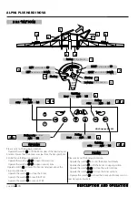
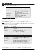
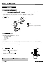
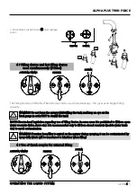
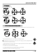
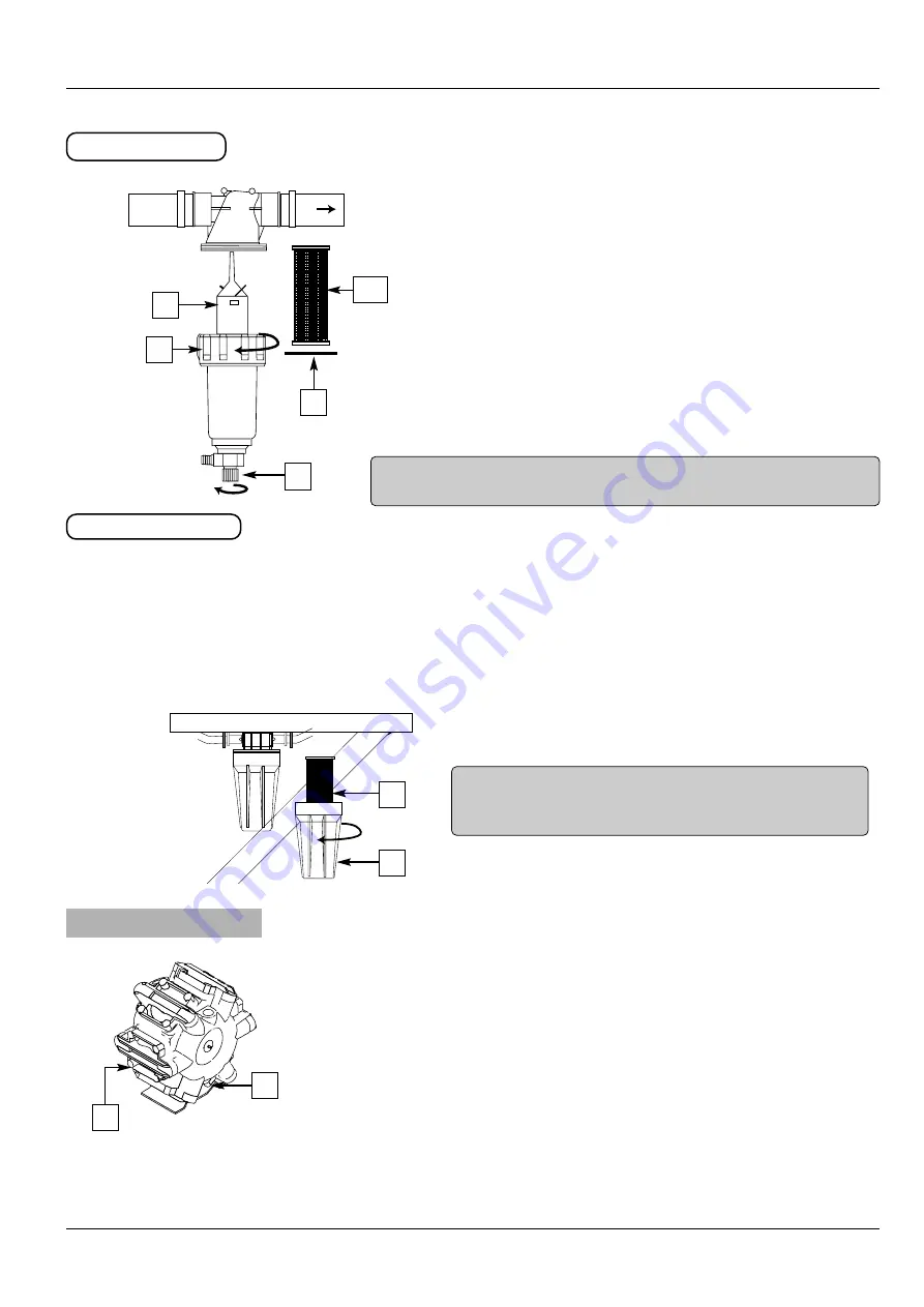
The delivery filter is located at the left-hand side of the machine.
Prior to any spraying, it is essential to put filter element into the
filter.

- Undo the nut ((1

1)) to remove the bowl

- Check the filter element  ((2

2)) , seal ((3

3)) and the  tube  ((4

4)) 

The cleaning  filter is automatic, for this purpose :

- Undo gently the draining valve ((5

5)) , the impurities are emptied

out

VERS RAMPE

D

D e

e ll ii vv e

e rr yy   ff ii ll tt e

e rr

II n

n - ll ii n

n e

e   ff ii ll tt e

e rr ss

3

3-

7

7

-

3

3

P

PU

UM

MP

P

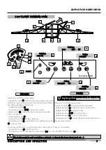
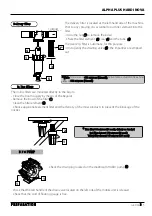
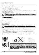
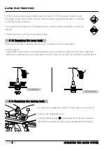
- Check the drain plug located on the diaphragm HARDI pump ((3

3))

- Check that the red handle of the drain valve located on the left side of the mobile unit is released
- Check that the cord of floating gauge is free.

** W

Wh

hiitte

e filter element 6

60

00

0 m

miiccrro

on

nss ((3

32

2m

me

essh

h)),,

delivered as standard 

Blue filter

element 3

30

00

0 m

miiccrro

on

nss ((5

50

0m

me

essh

h))

TO BOOM

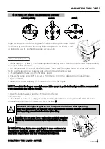
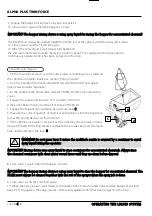
The in-line filters are mounted directly to the boom
- Close the boom supply by means of the Regulor.
- Remove the bowl of the filter ((1

1))

- Clean the filter element ((2

2)) 

- Choose appropriate element filter and the density of chemical products to prevent the blockage of the
nozzles.

** 

b

bllu

ue

e ffiilltte

err 3

30

00

0 m

miiccrro

on

nss ((5

50

0 m

me

essh

h)),, d

de

elliivve

erryy aass ssttaan

nd

daarrd

d

R

Re

ed

d ffiilltte

err e

elle

em

me

en

ntt 1

17

75

5 m

miiccrro

on

nss ((8

80

0 m

me

essh

h))

Y

Ye

ellllo

ow

w ffiilltte

err e

elle

em

me

en

ntt 1

14

40

0 m

miiccrro

on

nss ((1

10

00

0 m

me

essh

h))

1

2*

3

4

5

1

1

1

2

Содержание ALPHA PLUS 3500

Страница 1: ...EVRARD G GR RO OU UP PE E HARDI Reference 677833 Edition 07 05 OPERATING and MAINTENANCE Manual H A R D I H A R D I N O N O V V A A ...

Страница 2: ... 2 6 2 HEATING 2 6 3 AIR CONDITIONING 2 7 ENGINE 2 7 1 ENGINE ACCESS 2 7 2 STARTING THE ENGINE 2 7 3 ENGINE ACCELERATOR 2 7 4 STOPPING THE ENGINE 2 8 ADVANCE CONTROL 2 8 1 DRIVER S CONTROL LEVER 2 8 2 BRAKE ENGINE 2 8 3 PARKING BRAKE 2 8 4 COMBINED EMERGENCY PARKING BRAKE 2 8 5 SPEED SELECTOR FAST Speed SLOW Speed INTERMEDIATE Speed 2 9 WHEEL STEERING 2 9 1 DESCRIPTION 2 9 2 TWO WHEEL STEERING 2 9...

Страница 3: ...am 4 2 Use the Manifold valve system 4 3 Top operate the soraying function Electric operated MANIFOLD valves if fitted Pictograms GREEN disc pressure 4 4 Filling hand washing tank and rinsing tank 4 5 Filling with suction filling device if fitted 4 6 Filling with fast filling device if fitted 4 7 Filling device and fast filling device used simultaneously if fitted 4 8 Use of Quick coupler for exte...

Страница 4: ... condenser 5 2 7 EVERY 50 HOURS 463 Diaphragms pump Wheels Chassis and boom 5 2 8 EVERY 250 HOURS Hydraulic oil filters Carbon cab filters Triplet 5 2 9 EVERY 500 HOURS Air conditioning GVA Aluminium boom HAZ Boom adjustment 5 2 10 EVERY 1000 HOURS OR ANNUAL Nitrogen accumulator Valves ans diaphragms Battery 5 2 11 OCCASIONAL MAINTENANCE Level indicator adjustment Nozzle tubes and fittings Cone ch...

Страница 5: ...EEL MOTORS Standard brake version ACTION ON WHEEL MOTORS With combined brake version ACTION ON WHEEL MOTORS With Dyna version ACTION ON THE ADVANCING HYDROSTATIC PUMP 7 2 3 BOOM CONTROL DISTRIBUTOR 7 2 4 HYDRAULIC CIRCUIT Combined brake 7 3 SPRAYING CIRCUIT 7 3 1 PUMP DOES NOT PRIME 7 3 2 FOAM FORMS 7 3 3 NO ADMIXTURE OF PRODUCTS 7 3 4 INCORRECT SPRAYING 7 3 5 NO SPRAYING 7 3 6 VOLUME HA CANNOT BE...

Страница 6: ...uirements stipulated in EEC Directive 89 392 CE 91 368 CE et 93 368 CE The following standards have been taken into account in order to implement according to normal practice the health and safety regulation laid down in EEC Directives EN 292 1 EN 292 2 In addition the owner of the machinery is obliged to keep this manual throughout the life of the machine and in the event of resale to pass it on ...

Страница 7: ...V E E R R Y Y R R E E P P O O R R T T T Th he e d de el li iv ve er ry y r re ep po or rt t g gi iv ve en n w wh he en n t th he e m mo ob bi il le e u un ni it t i is s d de el li iv ve er re ed d m mu us st t b be e r re et tu ur rn ne ed d t to o H HA AR RD DI I E EV VR RA AR RD D B BP P 5 59 9 7 77 75 54 42 2 S SA AV VI IG GN NY Y L LE E T TE EM MP PL LE E C CE ED DE EX X F FR RA AN NC CE E d ...

Страница 8: ...rom the area Do not eat drink or smoke whilst spraying or working with contaminated equipment Immediately after spraying job wash and change the clothes In case of poisoning seek medical advice or call an ambulance Retain chemical label or container for identifi cation of chemical Keep childrens away from the sprayer Do not enter the sprayer tank If any portion of this instruction book remains unc...

Страница 9: ...gs The rinsing water must not no discharged into drains 1 1 6 6 C C L L E E A A N N I I N N G G T T H H E E S S P P R R A A Y Y E E R R 1 1 5 5 P P L L A A N N T T P P R R O O T T E E C C T T I I O O N N P P R R O O D D U U C C T T S S Safe use of sprayers is dependent on the user who must take the usual precautions when he is handling plant protection products and working with machine It is for e...

Страница 10: ...ALPHA PLUS TWIN FORCE 1 1 5 F F O O R R E E W W O O R R D D 1 1 7 7 N N I I T T R R O O G G E E N N A A C C C C U U M M U U L L A A T T O O R R OLAER OPERATING INSTRUCTIONS CE 109294 1 ...

Страница 11: ...ALPHA PLUS TWIN FORCE 1 1 6 F F O O R R E E W W O O R R D D ...

Страница 12: ...ALPHA PLUS TWIN FORCE 1 1 7 F F O O R R E E W W O O R R D D ...

Страница 13: ...ALPHA PLUS TWIN FORCE 1 1 8 F F O O R R E E W W O O R R D D ...

Страница 14: ... O O N N 2 2 D DE ES SC CR RIIP PT TIIO ON N O OF F A AL LP PH HA A S SP PR RA AY YE ER R Mirrors Suction Deliveryfilter Remotevalves Hydraulicdistributors connectionbox Frontworkslights Externalsprayingpumpswitch Electricaccelerator Identification plate Fusesbox Levelindicator Rinsingtank Main tank rinsing nozzle Chemicalfiller SMARTValves Handwashtank Ladder Screenwashreservoir Fueltank Transpor...

Страница 15: ...ook Spraying circuit drained with com pressed air winter period S SP PR RA AY YE ER R D DR RA AI IN NE ED D A AC CI IE ER R H HA AU UT TE E L LI IM MI IT TE E E EL LA AS ST TI IQ QU UE E N NE E P PA AS S P PE ER RC CE ER R N NE E P PA AS S S SO OU UD DE ER R H HI IG GH H S ST TR RE EN NG GT TH H S ST TE EE EL L N NO O D DR RI IL LL LI IN NG G N NO O W WE EL LD DI IN NG G STAHLMITHOCHELASTISCHEMWID...

Страница 16: ...C C A A T T I I O O N N cold marking of serial no HYDROSTATIC PUMP PLATE CAB PLATE ENGINE PLATE HYDRAULIC WHEEL PLATE The information relating to the identification of the self propelled ALPHA appears on a plate placed on the right hand side of the machine serial number type of model manufacturing date capacity of main tank empty and full weights IDENTIFICATION PLATES ...

Страница 17: ...ection indicator warning lamp Position lamp and dipped beam control lamp Head lamp main beam Rev counter and hour meter Hazard warning light switch Multi function control switch Horn Pre Heating light Fuel gauge Rotating amber warning beacon swit ch Engine temperature gauge Engine temperature and coolant gauge light When the machine is stopped the ladder is at low position To raise automatically t...

Страница 18: ... selector switch rotating Throttle switch 20 Anti skid switch optional 19 Not used Road security switch Ignition switch 21 Not used 22 Not used 23 Not used Liquid pump engagement switch Road security lamp 14 Oil pressure control control lamp combined brake Joystick forward reverse Hydraulic and spraying control Isolator warning lamp 24 14 24 Not used 21 2 2 5 5 2 2 C CO ON NS SO OL LE E O O P P T ...

Страница 19: ...fan switch air conditioning Air conditioning air vents 2 2 6 6 D DR RI IV VE ER R S S C CO OM MF FO OR RT T 2 2 6 6 1 1 S SE EA AT T As this is mounted on hydraulic shock absorbers and integrated longituginal suspension it protects the dri ver from shaking which inevitably occurs during driving The various position adjustments made by means of identifiable levers improve comfort The body contoured...

Страница 20: ... 2 6 6 3 3 A AI IR R C CO ON ND DI IT TI IO ON NI IN NG G Air conditioning of cab is provided by acompressor driven by the DEUTZ engine The cooling unit is fitted under the cab roof Adjust the temperature by means of the thermostat 1 16 6 Set air conditioning switch 1 15 5 on position ON P Pr re es ss s s sw wi it tc ch h 1 14 4 o on n p po os si it ti io on n 1 1 Set heating thermostat 9 9 on low...

Страница 21: ...uel gauge Hydraulic reservoir oil level For futher details see the MAINTENANCE section of this manual and the engine instruction book Place the joystick control lever in the neutral position A position detector ensures safety when starting Turn the ignition key to pos 1 1 the three warning lamps light up and the Cut off battery goes off Open the upper bonnet Operate the handle 1 1 and lift up the ...

Страница 22: ...E E W WA AR RN NI IN NG G L LA AM MP P S ST TA AY YS S S ST TO OP P T TH HE E E EN NG GI IN NE E I IM MM ME ED DI IA AT TL LY Y 2 2 7 7 3 3 E EN NG GI IN NE E A AC CC CE EL LE ER RA AT TO OR R Place the joystick lever to the neutral position Réduce engine speed before stopping in order to stabilize the engine temperature Turn the selector to position parking brake P P The two parking brake warning...

Страница 23: ... 2 8 8 2 2 B BR RA AK KE E E EN NG GI IN NE E 2 2 8 8 A A D D V V A A N N C C E E C C O O N N T T R R O O L L 2 2 8 8 1 1 D DR RI IV VE ER R S S C CO ON NT TR RO OL L L LE EV VE ER R M Mo ov vi in ng g the self propelled forward by tilting the control lever forward M Mo ov vi in ng g the self propelled reverse by tilting the control lever back B Br ra ak ki in ng g and s st to op pp pi in ng g the...

Страница 24: ...ssure the parking brake will engage automatically 2 2 8 8 4 4 C CO OM MB BI IN NE ED D E EM ME ER RG GE EN NC CY Y P PA AR RK KI IN NG G B BR RA AK KE E On some models the sprayer is fitted with a combined emergency and par king brake which can be variable proportioned On this model the opera ting pedal 1 1 is placed on the floor This manoeuvre can also be proportioned in order to apportion the us...

Страница 25: ...lly for spray in the field when driving uphill in slippery condition where change in weight distribution will cause spinning front wheels Speed range 0 0 1 18 8 km h Used generally for spray in the field when driving downhill in slippery condition where change in weight distribution will cause spinning rear wheels Speed range 0 0 1 18 8 km h F FA AS ST T S Sp pe ee ed d S Sl lo ow w S SP PE EE ED ...

Страница 26: ... TI IO ON N 2 2 8 8 2 2 T TW WO O W WH HE EE EL L S ST TE EE ER RI IN NG G Set the switch to A AU UT TO O Turn the steering control so as to place the rear wheels in straight position the REAR warning lamp goes on In this operating mode only the front wheels can steer and the rear wheels remain straight 2 2 w wh he ee el l s st te ee er ri in ng g i is s o op pe er ra at ti in ng g F FR RO ON NT T...

Страница 27: ... steering Release the pedal Turn the steering control so as to return the rear wheels to the straight position REAR and FRONT warning lamp light up Green warning lamp goes out 4 4 w wh he ee el l s st te ee er ri in ng g i is s o op pe er ra at ti in ng g 2 2 w wh he ee el l s st te ee er ri in ng g i is s o op pe er ra at ti in ng g In this operating mode the front and rear wheels steer at the sa...

Страница 28: ...R RE EA AR R warning lamp goes on Press the 4 wheel pedal Turn the steering control so as to put the rear wheels position is required The warning lamp R RE EA AR R goes out Release the pedal In this operting mode only the front wheels can steer and the rear wheels remain in the same position For returning to 4 wheel steering Set the switch to AUTO The warning lamp 4 wheel steering goes out Turn th...

Страница 29: ...h on the switch A lamp indicates that the spray pump is engaged Operate the switch R RP PM M ref 1 1 to reduce speed to minimum before engaging 2 2 1 10 0 S SP PR RA AY Y P PU UM MP P W WA AR RN NI IN NG G I IF F S SP PR RA AY Y P PU UM MP P I IS S E EM MP PT TY Y I IT T I IS S E ES SS SE EN NT TI IA AL L T TO O P PR RI IM ME E I IT T ...

Страница 30: ...t t a ar re ea a B Be ef fo or re e a an ny y m mo ov ve em me en nt t o of f t th he e b bo oo om m m ma ak ke e s su ur re e t th ha at t n no o o os st ta ac cl le e i is s c cl lo os se e t to o s sp pr ra ay ye er r p po os st t a an n i in nd di iv vi i d du ua al l r ro oa ad d e et tc c R Re ed du uc ce e e en ng gi in ne e s sp pe ee ed d b be ef fo or re e u us si in ng g t th he e b bo ...

Страница 31: ...e outer sections Operate the switch 2 2 3 3 to close the inner sections Operate the switch 1 1 to lower the boom until boom rests on rear transports brackets F FO OL LD DI IN NG G U Un nf fo ol ld di in ng g o ou ut te er r sections r ri ig gh ht t and l le ef ft t R Ra ai is si in ng g of the boom L Lo ow we er ri in ng g of the boom S Sl la an nt ti in ng g R RI IG GH HT T hand side tilt D DO OW...

Страница 32: ...inner sections Operate the switch 1 1 to lower the boom until boom rests on rear transports brackets F FO OL LD DI IN NG G T Th he e f fo ol ld di in ng g m mo ov ve em me en nt t s sh ho ou ul l b be e c ca ar rr ri ie ed d o ou ut t o on n l le ev ve el l g gr ro ou un nd d U Un nf fo ol ld di in ng g i in nn ne er r sections r ri ig gh ht t and l le ef ft t NOVA Hydraulic 4600 F Fo ol ld di in ...

Страница 33: ...ur 3 872 CFM A boom hour The air speed must be adjusted to the spray job The tables below give a guide line Air asssistance Low Medium High H Very high VH Air speed m s 5 10 10 20 20 30 30 35 Fan r p m 400 1000 1000 1900 1900 2700 2700 3100 Oil pressure bar Boom 18 m 20 40 40 75 75 125 125 180 Boom 20 21 m 25 50 50 90 90 150 150 200 Boom 24 28 m 30 70 70 140 140 190 190 240 l l l l 2 2 1 13 3 1 1 ...

Страница 34: ...he wider the range of air speeds that can reduce drift A At t h hi ig gh he er r w wi in nd d s sp pe ee ed ds s More air is needed on the sprayer and it is advisable to drive more slowly and use minimum boom height 40 cm 16 in N NO OT TE E Too high air speed over bare ground low crop can cause reflection of the spray liquid and leave dust on the leaves which can again reduce the effect of the pla...

Страница 35: ... The angling feature is ideal to help opening the canopy and improve penetration If you follow the crop movement as you are varying the angling you will find at certain settings the crop will open more for penetration If wind speed wind direction or for some reason forward speed changes during spraying the optimum angling is likely to change too Be aware that with certain combinations of air speed...

Страница 36: ...the other countries If you want some local advice you are very welcome to contact the TWIN application expert at the HARDI importer or daughter company in your country The volume rate can generally be reduced to half of what is applied with a conventional sprayer but with a minimum of 50 60 l ha at 7 8 km h Exceptions are of course liquid fertiliser and herbicides whose selectivity is based large ...

Страница 37: ...ALPHA PLUS HARDI NOVA D D E E S S C C R R I I P P T T I I O O N N A A N N D D O O P P E E R R A A T T I I O O N N CHAPTER 2 2 24 ...

Страница 38: ...ALPHA PLUS HARDI NOVA D D E E S S C C R R I I P P T T I I O O N N A A N N D D O O P P E E R R A A T T I I O O N N CHAPTER 2 2 25 ...

Страница 39: ...tivates the appropriate stored parameters for speed and air air angle HARDI NOVA see Nova manual 2 4 S2 S1 S3 S4 3 1 1 2 3 4 5 R3 R1 R2 R1 FRONT RIGHT FRONT LEFT REAR LEFT REAR RIGHT The anti skid system has to be operated when the machine works in hard and hilly conditions CAUTION Switch on the anti skid system before starts slipping of the machine Push on the switch 1 1 control light 2 2 lights ...

Страница 40: ...nstrument panel Check the lighting and signals W WA AR RN NI IN NG G After stopping the engine turn the battery cut off control vertically to pre vent battery discharge during a lengthly stoppage OFF ON 3 3 2 2 D DI IE ES SE EL L T TA AN NK K The 3 32 20 0 litre diesel oil tank is located on the right hand side Before filling the tank you must Stop the engine Do not smoke Carefully clean the tank ...

Страница 41: ...oir A thermometer indicates the oil tempera ture This 6 60 0 litre reservoir is located under the cab The filler cap is situated on the reservoir on the left hand side of the machine 1 1 Carefully clean the tank cap Do not let any impurities in use a funnel if necessary Take care do not let any water in the oil tank Always fill the reservoir with hydraulic oil of the same characteris tic as those ...

Страница 42: ... E E S S 3 3 6 6 1 1 P PR RE ES SS SU UR RE E Check wheels and bolts using a torque wrench after 1 1 hrs 2 2 hrs and 8 8 hrs of operation and then periodically 3 3 6 6 2 2 B BO OL LT TS S T TI IG GH HT TI IN NG G N Ne ev ve er r l lu ub br ri ic ca at te e w wh he ee el ls s b bo ol lt ts s o or r t th hr re ea ad ds s I It t i is s e es ss se en nt ti ia al l t to o f fo ol ll lo ow w r re ec co ...

Страница 43: ...g 3 3 7 7 2 2 F FI IL LT TE ER RS S S Su uc ct ti io on n f fi il lt te er r Undo the nut 1 1 and remove the bowl Clean element 2 2 in clean water Check the presence of the seal 3 3 Reassemble the filter unit White color element filter 3 32 2 mesh delivered as standard Choosing the t ty yp pe e o of f n no oz zz zl le e v vo ol lu um me e h ha a s sp pe ee ed d and p pr re es ss su ur re e refer t...

Страница 44: ...le unit is released Check that the cord of floating gauge is free W Wh hi it te e filter element 6 60 00 0 m mi ic cr ro on ns s 3 32 2m me es sh h delivered as standard Blue filter element 3 30 00 0 m mi ic cr ro on ns s 5 50 0m me es sh h TO BOOM The in line filters are mounted directly to the boom Close the boom supply by means of the Regulor Remove the bowl of the filter 1 1 Clean the filter e...

Страница 45: ...le es s w wi it th h o ot th he er r c ca ap pa ac ci it ti ie es s t th he e n no oz zz zl le e o ou ut tp pu ut t i in nc cr re ea as se es s a as s t th he e n no oz zz zl le es s w we ea ar r 3 3 7 7 5 5 A AD DJ JU US ST TI IN NG G T TH HE E P PE EN ND DU UL LU UM M E EF FF FE EC CT T L LP PA A B BO OO OM MS S P PO OS SI IT TI IO ON N 1 1 3 3 The boom is always kept horizontal Use this posi ti...

Страница 46: ... B B 5 Place a suitable tool in the hole in the turn buckle and use the tool to rotate the turn buckle Clockwise rotation The turn buckle becomes longer 7 Adjust the steering arm to obtain the correct setting measured dis tance d d 8 Always use the same position for both bottom steering arms 9 Check the distance d d re adjust if necessary 10 Tighten nuts B B and A A again d A C B A Lift frame Cent...

Страница 47: ...ALPHA PLUS HARDI NOVA P P R R E E P P A A R R A A T T I I O O N N CHAPTER 3 3 8 ...

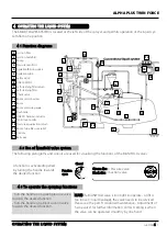
Страница 48: ...nction Turn the handle on a black suction valve towards the desired function 4 4 O OP PE ER RA AT TI IN NG G T TH HE E L LI IQ QU UI ID D S SY YS ST TE EM M The SMART VALVES SYSTEM is located at the left side of the sprayer and permits operation of the liquid sys tem from one position 4 4 1 1 F Fu un nc ct ti io on n d di ia ag gr ra am ms s 19 19 18 12 10 11 8 20 20 20 2 20 21 3 11 15 9 7 17 17 6...

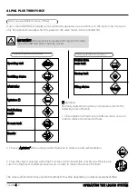
Страница 49: ...hi in ng g n no oz zz zl le e T To o m ma ai in n t ta an nk k T Tr ra an ns sf fe er r Pictograms GREEN disc Pressure S Su uc ct ti io on n f fr ro om m m ma ai in n t ta an nk k R Ri in ns si in ng g t ta an nk k F Fi il ll li in ng g d de ev vi ic ce e Pictograms BLACK disc Suction 2 Choose A Ag gi it ta at ti io on n when using powder chemicals in order to avoid sedimentation 3 Close the valve...

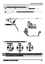
Страница 50: ... g t ta an nk k a an nd d r ri in ns si in ng g t ta an nk k B W WA AR RN NI IN NG G A Av vo oi id d c co on nt ta am mi in na at ti io on n o or r p pe er rs so on na al l i in nj ju ur ry y D Do o n no ot t o op pe en n s su uc ct ti io on n v va al lv ve e t to ow wa ar rd ds s S Su uc ct ti io on n F Fi il ll li in ng g D De ev vi ic ce e u un nl le es ss s p pu um mp p i is s r ru un nn ni in...

Страница 51: ...se B B to Suction Manifold 2 Engage diaphragm pump and set P T O revolutions at 540 r min or 1000 r min depending on pump model 3 Turn handle on Suction Manifold towards Filling Device 4 The tank is now filled with water Keep an eye on the liquid level indicator 5 Turn handle on Suction Manifold away from Filling Device to discontinue filling process Then disengage pump 6 Disconnect suction tube B...

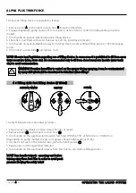
Страница 52: ... t to o o ov ve er rf fi il ll l t th he e t ta an nk k The Filling Device and the Fast Filling Device can be used simultaneously this gives even bigger filling capacity ALPHA PLUS TWIN FORCE O OP PE ER RA AT TI IN NG G T TH HE E L LI IQ QU UI ID D S SY YS ST TE EM M CHAPTER 4 4 5 P PR RE ES SS SU UR RE E S SU UC CT TI IO ON N A B 7 Disconnect suction tube B B and replace cover W WA AR RN NI IN NG...

Страница 53: ...nd set P T O revolutions to 540 r min or 1000 r min depending on pump odel 4 Add the chemicals through the main tank hole 5 When the spray liquid is well mixed turn handle on the Smart Valve towards Spraying position Keep P T O engaged so the spray liquid is continuously agitated until it has been sprayed on the rop W WA AR RN NI IN NG G D Do o n no ot t l le ea av ve e t th he e s sp pr ra ay ye ...

Страница 54: ...IN NS SI IN NG G P PR RE ES SS SU UR RE E S SU UC CT TI IO ON N To get access to the HARDI FILLER grab the handle and drag the HARDI FILLER the whole way down Due to the spring loaded suspension it will stay in this position After use it is pushed the whole way up again Filling of liquid chemicals W WA AR RN NI IN NG G D Do o n no ot t p pr re es ss s l le ev ve er r B B u un nl le es ss s t th he...

Страница 55: ... o r ri in ns se e t th he e h ho op pp pe er r f fo or r o on nc ce en nt tr ra at te ed d c ch he em mi ic ca al l T Th he e F FI IL LL LE ER R m mu us st t a al lw wa ay ys s b be e c cl le ea an ne ed d t to og ge et th he er r w wi it th h t th he e r re es st t o of f t th he e s sp pr ra ay ye er r w wh he en n t th he e s sp pr ra ay y j jo ob b i is s d do on ne e 9 Close valve A and the ...

Страница 56: ...se Adjustable Agitation to adjust the needed amount of agitation related to selected praying volume A AG GI IT TA AT TI IO ON N R RI IN NS SI IN NG G P PR RE ES SS SU UR RE E S SU UC CT TI IO ON N The incorporated rinsing tank can be used for two different purposes A A In field diluting of remaining spray liquid residue in the spraying circuit for spraying the liquid in the field before cleaning t...

Страница 57: ...letely after rinsing in compliance with local legislation For this purpose Pull the red handle located on the left side of the sprayer in order to empty the main tank completely When this is released the valve closed again To keep it open secure the cord around the locating device 4 4 1 13 3 E Em mp pt ty yi in ng g t th he e m ma ai in n t ta an nk k VALVE OPEN VALVE CLOSED It is advisable to emp...

Страница 58: ... 6M M2 20 01 12 2C C 1 12 2 5 5 l 1 14 4 0 0 l Hydrostatic transmission 6 60 0 litre Hydraulic system General lubrication Coolant 2 20 0 litre approx R Ru ub bi ia a 4 44 40 00 0 A AP PI I C CG G 4 4 A AP PI I S SG G A AC CE EA A E E2 2 B B2 2 A A2 2 9 96 6 E EQ QU UI IV VI IS S Z ZS S 4 46 6 A AF FN NO OR R N NF F E E 4 48 8 6 60 03 3 H HV V I IS SO O 6 67 74 43 3 4 4 H HV V M Mu ul lt ti is s E ...

Страница 59: ...r Check the refrigerant level R134a of air conditioning Replace the hydraulic filter Dyna only Every 1 10 00 00 0 h Drain diesel oil tank and diesel oil tank strainer or A AN NN NU UA AL L Change oil in hydraulic reservoir Check the valves and diaphragms in diaphragm pumps Check the engine air intake check for leakage and pre heating plugs Change the safety air intake cartridge Check the electroly...

Страница 60: ...PTER 5 5 3 5 5 2 2 5 5 A A L L U U M M I I N N I I U U M M B B O O O O M M M M A A I I N N T T E E N N A A N N C C E E Thigten the screws A A after 1 10 0 and 5 50 0 hours of use then periodically every 1 15 50 0 hours Loosen the lock nuts B B before tighten the nuts C C ...

Страница 61: ...m depends on the spray ap plication Frequenc y of cleaning must be increase in the case of dust y environment nt 1 1 de ti Engine oil level Fuel level C Co oo ol la an nt t L Le ev ve el l When the engine is cold coolant level shoud be above the mark on the sight glass 1 1 Unscrew the filler cap 2 2 and fill up coolant up if necessary This chapter discribe operations maintenance on DEUTZ engine Re...

Страница 62: ...is located on the engine air intake If the red signal 1 1 is fully visible when the engine is off you must clean the filter cartridge Act as follow Undo clips 2 2 and take off hood 3 3 Blow out from inside out with dry compressed air max 5 bar In difficult cases tap out taking care not to damage the cartridge After carrying out service work reset the signal by pressing the button 4 4 on the servic...

Страница 63: ...ain and check for leaks 1 1 ALPHA PLUS HARDI NOVA M M A A I I N N T T E E N N A A N N C C E E CHAPTER 5 5 6 C Ch ha an ng gi in ng g F Fu ue el l F Fi il lt te er r 1 1 1 1 Undo fuel filter cartridge 1 1 with commercial tool and spin off Apply light film of oil to rubber gasket of the new fuel filter cartridge Screw in the new cartridge finger tight against the gasket Check that the cartridge is s...

Страница 64: ... plug from crankcase 3 3 Drain off the coolant Rinse the cooling circuit with pure water Open the radiator cap 4 4 and fill coolant up to maximum Close radiator cap 4 4 then open the expansion tank 5 5 Add coolant see chapter 5 Coolant Level Start and run the engine up to normal operating temperature to open the thermostat housing Check level and add coolant if necessary Open the heater valve in c...

Страница 65: ... the sight glass situated on the reservoir An audible warning located on under the instrument panel indicates a lack of oil in the hydraulic system Check the hydraulic circuit immediately for leaking and refill oil A A L L W W A A Y Y S S U U S S E E A A S S I I M M I I L L A A R R H H Y Y D D R R A A U U L L I I C C O O I I L L h hy yd dr ra au ul li ic c o oi il l l le ev ve el l Remove the 4 sc...

Страница 66: ...the pump 4 46 63 3 d di ia ap ph hr ra ag gm ms s p pu um mp p W Wh he ee el ls s Check the tyre pressure wich should be in accordance with the following table C Ch ha as ss si is s a an nd d B Bo oo om m 300 95R46 3 6 460 85R34 1 6 480 70R38 1 6 600 70R30 1 6 520 70R38 1 6 ALPHA 3 34 40 00 0 and 4 41 10 00 0 bar 6 60 0 daN m 442 4 lbf ft Cast solid collar nut 3 35 5 daN m 258 lbf ft ...

Страница 67: ...ALPHA PLUS HARDI NOVA M M A A I I N N T T E E N N A A N N C C E E CHAPTER 5 5 10 5 5 1 1 2 2 3 3 C Ch ha as ss si is s a an nd d b bo oo om m Transport bracket ...

Страница 68: ...e er rs s 5 5 2 2 9 9 E EV VE ER RY Y 250 H HO OU UR RS S I It t i is s e es ss se en nt ti ia al l t to o u us se e t th he e m ma ak ke er r s s g ge en nu ui in ne e h hy yd dr ra au ul li ic c o oi il l f fi il lt te er rs s The filter cartridges 1 1 are located on the each side of the machine Unscrew the filter cartridges Lightly oil the joint Screw on the new filter cartridge and turn 1 2 tu...

Страница 69: ...rational condition of the filtration system is of primary importance for the user s health C Ca ar rb bo on n C Ca ab b F Fi il lt te er rs s The carbon cab filters are located on either side of the cab close to the windscreen Act as follows Unscrew the fixing screw 1 1 Pull out the carbon filter cover 2 2 to extracting the carbon filter 3 3 Replace the new carbon cab filters reference 2 27 78 82 ...

Страница 70: ...w on the filter element housing Check for leaks A seal kit is available ref 2 24 48 81 12 28 8 1 1 2 2 3 3 It is recommended to change the deshydrater filter every 2 years ref 278284 Date of the fluorescent trace A fluorecent tracor is mixed with refrigerant Leaks of gas is detected with a ultraviolet lamp This fluorescent trace is active for 5 years see the label stack in the cab A Ai ir r c co o...

Страница 71: ...t the ram Position the rod at the maximum position Adjust the hinge B B to get the outer section in contact with the screw stop A A Screw on 2 turn the hinge B B to lock the assembly B B A A C C B B A A Check the tension of the air conditioning belt for this purpose Unscrew the locknut 1 1 of the belt tightener Screw the nut 2 2 to tension the belt and re fit the locknut Check the tension after 1 ...

Страница 72: ... fo ol ld di in ng g a ad dj ju us st tm me en nt t 1 1 S Su us sp pe en ns si io on n s sp pr ri in ng g t te en ns si io on n Loosen the counter nuts A A in either side and adjust the tension of the vertical springs on the bolts B B to suit the boom weight The adjustment is correct when the guide Tighten the counter nuts again A A A A B B F F E E D D C C H HA AZ Z B Bo oo om m a ad dj ju us st t...

Страница 73: ...y y t th he e b bo oo om m a an nd d L Lo oc ck k t th he e b bo oo om m Y Yo ou u m mu us st t e en ns su ur re e t th ha at t t th he er re e i is s n no o r re es si id du ua al l h hy yd dr ra au ul li ic c p pr re es ss su ur re e i in n t th he e a ac cc cu um mu ul la at to or r a an nd d u us se e t th he e O OL LA AE ER R c ch he ec ck ki in ng g i in nf fl la at ti io on n t to oo ol ls ...

Страница 74: ... battery and place the latter in a well ventilated place free from any source of sparks and flames no smoking before charging it Disconnect the battery terminals and the alternator before to carry out electric welding on the machine A defective battery can damage electronic equipment Clean the battery terminals if necessary Remove valve cover 1 1 before changing the valves 2 2 Note their orientati...

Страница 75: ...reading shoud be checked regulary When the tank is empty the float should lie on the stop pin of the rod and the O ring on the indicator should be positionned at the top position line A A If any deviation is found pull out the plug B B loosen screws C C and adjust the length of the cord A A B B C C N No oz zz zl le e t tu ub be es s a ab bd d f fi it tt ti in ng gs s Poor seals are usually caused ...

Страница 76: ...semble again Assemble the valve assembly again using a new valve seat E E Lubricate O rings F F before assembly Fit clip A A again E E F F Use eye face protection mask when dis mantling the tank drain valve Do not enter the inside of the tank the parts can be changed from underneath the tank Periodically check the distribution valves for proper sealing Do this by running the sprayer with clean wat...

Страница 77: ... peroxide 10 vol Ammoniac diluted to 15 Spot of oil dirty oil tar Fats Use lightly Essence F Soapy water Spray aerosol stain remover for carpet Mud Stain remover for carpet soapy water Stick adhesive Essence A Rust Hydrochloric acid dilued to 5 and rinsing with water Theses recommendations are indicat and no exhaustive Use others cleaning products after a test beforehand A Ad dj ju us st tm me en ...

Страница 78: ...king pressure measurement P P2 2 Connector for feed pressure R R Adjustment screw for feed pressure S S Suction port A A R R P P2 2 A A B B Fill the oil reservoir with fresh clean oil to the top of sight glass Fill the pump housing with oil through the drain pipe D which is dismantled at the tank connection Reconnect and tighten Check the oil level in the gear box Remove the drain hose D from the ...

Страница 79: ...ay y d de ev vi ic ce e A A A A B B To ensure optimal damping and stability of the boom control of the rubber dampers is necessary at regular intervals 1 Unfold the boom 2 Loosen and unscrew with one turn the jag nut A A 3 Loosen the rubber damper B B 3 Loosen the nut C C 4 Retain nut D D against the jag nut A A 5 Unscrew the rubber damper B B from the bolt head E E 6 Grease the top of the new dam...

Страница 80: ...ing and stability of the boom control of the spring washers is necessary at regular intervals 1 Unfold the boom and remove the boom locking device 2 Loosen and remove pins A A and B B 3 Remove counter nut C C 4 remove spring washers D D and E E R Re en ne ew wa al l o of f s sp pr ri in ng g w wa as sh he er rs s B B C C D D A A E E A A x8 x6 5 Place new spring washers respecting the right positio...

Страница 81: ...sequent adjustment will be required very seldom A A A A 1 Unfold completely the boom 2 Loosen big nut B B 3 Loosen the 2 nuts C C 4 The boom central section must be suppor ted to release the central spring 5 Grasp around the spring D D and rotate the whole spring arrangement to regulate the lenght of it To adjust the lenght Clockwise rotation The spring arrangement becomes longer and the steering ...

Страница 82: ...ld completely the boom 1 Remove pendulum lock A A from lift frame 2 Place lift frame B B and pendulum C C on level position 3 Make sure that the pendulum damping system D D is perpendicular to the pendulum 4 Loosen nuts E E 5 Place a suitable tool in the hole in the turn buckle and use the tool to rotate the turn buckle Clockwise rotation The turn buckle becomes longer 6 Adjust the steering arm to...

Страница 83: ...main tank See the antifreeze instructions to obtain sufficient protection from freezing Spray for a few moments at the nozzles to protect the nozzles Engage the pump and operate all valves and functions on the Manifold operating filler etc allowing the anti freeze mixture to be distribued around the entire circuit Open the operating unit main on off valve and distribution valves so the anti freeze...

Страница 84: ...onnect the Hardi Nova control boxes Drain oil and coolant of the engine check V belts tension and check replace engine air filter Replace carbon cab filters Replace all hydraulic filters and drain the hydraulic oil tank Check the air conditioning Check all hydraulic and electric functions Drain and rinse the spraying circuit with clean water Check the spraying filters and nozzles Check all Twin fu...

Страница 85: ...ALPHA PLUS HARDI NOVA M M A A I I N N T T E E N N A A N N C C E E CHAPTER 5 5 28 ...

Страница 86: ...24 4 10A Option after ignition supply 2 25 5 7 5A Engine accelerator 2 26 6 5A Agitation no agitation valve 2 27 7 20A Working lights optional 2 28 8 10A Not used E 1 E 2 E 3 E 4 E 5 E 6 E 7 E 8 E 9 E 10 1 2 3 4 5 6 7 8 9 10 11 12 13 14 15 16 17 18 19 20 21 22 23 24 25 26 27 28 E E1 1 Clutch air conditioning compressor relay E E2 2 Air conditioning condenser relay E E3 3 Accelerator relay E E4 4 A...

Страница 87: ... 4 7 5A Horn F Fu u5 55 5 10A Flasher unit control F Fu u5 56 6 7 5A Right position lamps F Fu u5 57 7 7 5A Left position lamps F Fu u5 58 8 7 5A Right head lights Dipped beam F Fu u5 59 9 7 5A Left head lights Dipped beam F Fu u6 60 0 15A Head lights Main beam F Fu u6 61 1 7 5A Left direction indicator F Fu u6 62 2 20A Multi function switch and warning lights F Fu u6 63 3 10A Hardi Nova 12V elect...

Страница 88: ...AM M The compressor does not work The condenser do not work The evaporator do not work Check that the thermostat works correctly Check the relay E1 and fuse F1 of the compressor clutch Check the relay E2 and fuse F2 of the condenser controller Check that the binary pressure works correctly Check the gas pressure and that the refrigeration circuit is air tight Clean the condenser Check fuse n 3 The...

Страница 89: ...h Check the starter motor Check level of fuel in tank an diesel oil filters Check pre heating fuse n 15 Check pre heating plug Check the stopping unit Check fuse n 25 and accelerator unit PROBLEMS SOLUTIONS 6 6 1 1 3 3 E EN NG GI IN NE E 6 6 1 1 4 4 F FO OU UR R W WH HE EE EL LS S S ST TE EE ER RI IN NG G No signal from inductive sensor Faulty front or rear inductive sensor Faulty of hydraulic dis...

Страница 90: ...f the engine or hydraulic cir cuit it is essential to 1 CANCEL THE SETTING OF THE HIGH PRESSURE VALVE OF HYDROSTATIC PUMP 2 RELEASE THE FOUR BRAKES OF THE HYDRAULIC MOTOR Stop immediatly the engine Check the leak of the hydraulic circuit Fill the reservoir with the same characteristic hydraulic oil D D Slacken locknuts ref E E E E Completely unscrew the 2 Hc bolts situated in the safety nuts to ca...

Страница 91: ...of wheel motor Tighten the 2 counter nuts Torque setting 6 60 0 Nm Release the brake 1 Nm 0 74 lbft 2 2 A Ac ct ti io on n o on n w wh he ee el l m mo ot to or rs s S St ta an nd da ar rd d b br ra ak ke e v ve er rs si io on n A A On each wheel motor remove the centre rubber plug and fit parts refs 1 2 and 3 B B Position the M16 threaded rods on the hydraulic motor C C With release bar ref 3 comi...

Страница 92: ...achine you must Stop the engine Turn the locking device 3 3 down and place the handle of selector ver tically 4 4 Loosen the 2 plugs 5 5 mounted with restrictors Dyna hydraulic motor version Fit special plugs equipped with chains 6 6 to keep the brake hydraulic pressure After this fit the lever 7 7 and pump gently until the parking brake is completely released The machine can be towed on a distanc...

Страница 93: ...r Check the mechanical neutral position of the hydrostatic pump Check fuse n 16 Check the parking brake is deactivate Check by means the manual servo Check the feeder pressure about 30 bar Check the high pressure circuit Check the battery Check the voltage control unit Check hydraulic filters Check the H P valves Check the feeder pressure Check leak of internal componants hydrostatic pump motors e...

Страница 94: ...HA PLUS HARDI NOVA F F A A U U L L T T S S I I N N O O P P E E R R A A T T I I O O N N CHAPTER 6 6 9 3 6 6 2 2 4 4 H HY YD DR RA AU UL LI IC C C CI IR RC CU UI IT T C CO OM MB BI IN NE ED D B BR RA AK KE E ...

Страница 95: ... N NO O A AD DM MI IX XT TU UR RE E O OF F P PR RO OD DU UC CT TS S 6 6 3 3 4 4 I IN NC CO OR RR RE EC CT T S SP PR RA AY YI IN NG G Incorrectly positioned valves Insufficient pump delevery Suction filter clogged Check positions valves Accelerate the pump Clean suction filter Check connections and seals PROBLEMS SOLUTIONS Suction and delivery filters clogged Faulty pump Crushed piped Foreign body ...

Страница 96: ...polarities Check fuses FT1 FT8 and FR1 FR11 Check for mechanical jamming of valves Clean nozzles and spray circuit PROBLEMS SOLUTIONS Faulty limit switch of the regulating valve Filters Incorrect volume ha Inappropriate nozzles Adjustment of the manual volume regulating valve Clean filters Match the filter mesh to the spraying Adjust the machine speed Check programming of the REGULOR IV Check flow...

Страница 97: ...cuit Bleed the circuit Bleed the circuit with clean water Replace by a new pressure gauge if necessary 0 2 4 6 8 12 16 HARDI 284831 PROBLEMS SOLUTIONS REMOVAL REASSEMBLY 6 6 3 3 1 11 1 P PR RE ES SS SU UR RE E G GA AU UG GE E In case of power failure the pendulum device can be loc ked as follows 1 Unscrew nut A A 2 Remove O ring B B and coil C C 3 Screw completely nut A A to lock the pendulum C A ...

Страница 98: ...utor 268570 Pedal 73004401 Printed circuit equipped H Hy yd dr ra au ul li ic c e eq qu ui ip pm me en nt t CA75AA8002 Hydrostatic pump filter cartridge 786769 Hydraulic suction filter cartridge BO40DJ7250 Hydraulic reservoir plug F Fu us se es s 268127 Autofuse 2A 268417 Autofuse 3A 268330 Autofuse 5A 268027 Autofuse 7 5A 268160 Autofuse 10A 268028 Autofuse 15A 268418 Autofuse 20A 268313 Autofuse...

Страница 99: ...A AL LP PH HA A P PL LU US S T TW WI IN N F FO OR RC CE E L L I I S S T T O O F F M M A A I I N N P P A A R R T T S S CHAPTER 7 7 2 ...

Отзывы: