background image

ITEM #0373645

E124404

WOLCOTT CEILING FAN

MODEL #WO52BB5C

Questions, problems, missing parts?

 Before returning to your retailer, call or contact our 

customer service department at 

1-800-527-1292

, 8:30 a.m. - 5:00 p.m., CST, Monday - Friday.

Harbor Breeze® is a registered trademark of 
LF, LLC. All Rights Reserved.

Español p. 19

ATTACH YOUR RECEIPT HERE

Serial Number

Purchase Date

1

Содержание WO52BB5C

Страница 1: ...g parts Before returning to your retailer call or contact our customer service department at 1 800 527 1292 8 30 a m 5 00 p m CST Monday Friday Harbor Breeze is a registered trademark of LF LLC All Ri...

Страница 2: ...inserts Should this fan need to be returned to the factory for repairs it must be shipped in its original packaging to ensure proper protection against damage that might exceed the initial cause for r...

Страница 3: ...ned to accept only one 12 gauge house wire and two lead wires from the fan If your house wire is larger than 12 gauge or there is more than one house wire to connect to the two fan lead wires consult...

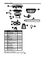
Страница 4: ...ounting Plate 1 B Motor Assembly 1 C Candelabra base 7 watt 4 Bulb D Blade Arm 5 E Blade 5 F Light Kit Fitter 1 G Glass Shade 4 H Candelabra base 60 watt 4 Bulb I Pull Chain Extension 2 J Motor Screw...

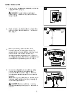
Страница 5: ...andelabra base 7 watt max bulbs for lighted housing 4 candelabra base 60 watt max bulbs for light kit DANGER When using an existing outlet box make sure the outlet box is securely attached to the buil...

Страница 6: ...ain connected to one another after they have been removed from the box If necessary disengage motor assembly B from J hook on mounting plate A so that motor assembly B can be separated from mounting p...

Страница 7: ...erly grounded and that a ground green or bare wire is present WIRING Warning If house wires are different colors than referred to in the following steps stop immediately A professional electrician is...

Страница 8: ...ARE GREEN wire from ceiling Fig 1B 1C FAN AND LIGHT CONTROLLED BY TWO WALL SWITCHES If you intend to control the fan and light with separate wall switches connect BLACK wire from fan to BLACK wire fro...

Страница 9: ...wo WHITE wires labeled INTERIOR LIGHT in the mounting plate A and the two molex connections one RED wire one WHITE wire at the top of the motor assembly B and connect these wires Fig 2 Make sure that...

Страница 10: ...ts EE completely Socket CC EE EE 2 B C A Socket Mounting Plate Nut x4 Hardware Used EE It is advisable to check that the wiring has been done correctly before proceeding Connect the male plug from the...

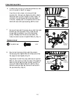
Страница 11: ...A Twist motor housing L to lock Insert the other two motor housing mounting screws FF and tighten all four motor housing mounting screws FF securely Fig 4 CAUTION Do NOT use power tools to avoid break...

Страница 12: ...Female Plug 8 F M Remove three switch housing screws M from light kit fitter F and set aside Then locate thumb screws DD provided in one of the hardware packs Partially insert thumb screws DD into hol...

Страница 13: ...overtighten thumb screws DD as glass may crack or break 9 13 9 G DD DD L Hardware Used The pull chain extensions I supplied in one of the hardware packs or custom pull chains extensions sold separatel...

Страница 14: ...fore trying to access bulbs C in lighted housing Replace access cover s with screws that were removed 1 Access Cover C 1 L The pull chain located on the switch housing has four positions to control fa...

Страница 15: ...he reverse switch in the UP position will result in upward airflow that can help move stagnant hot air off the ceiling area Fig 3B At least twice each year tighten all screws on fan Clean motor housin...

Страница 16: ...se 5 Turn power off Carefully loosen motor housing L and verify that mounting plate A is secure according to instructions on page 6 Excessive wobbling 1 Blades E are loose 1 Tighten all blade screws A...

Страница 17: ...conditions this warranty does not cover changes in brass finish rusting pitting tarnishing corroding or peeling Brass finish fans maintain their beauty when protected from varying weather conditions...

Страница 18: ...ew BB Fiber Blade Washer CC E3 Wire Connector DD Thumb Screw EE Mounting Plate Nut FF Motor Housing Mounting Screw GG Bushing REPLACEMENT PARTS LIST For replacement parts call our customer service dep...

Страница 19: ...e LF LLC Reservados todos los derechos Preguntas problemas faltan piezas Antes de regresar a la tienda llame o p ngase en contacto con nuestro departamento de servicio al cliente al 1 800 527 1292 de...

Страница 20: ...un electricista calificado o consulte una gu a de instalaci n el ctrica de h galo usted mismo disponible en Lowe s si no est familiarizado con la instalaci n el ctrica Aseg rese de que el lugar de ins...

Страница 21: ...aceptar s lo un cable de calibre 12 de la casa y dos cables principales del ventilador Si el calibre del cable de la casa es superior al 12 o hay m s de un cable de la casa para conectar a los cables...

Страница 22: ...ta 5 E Paleta 5 F Conectador para el juego 1 de luz G Pantalla de vidrio 4 H Bombilla de base 4 candelabro de 60 vatios 22 CONTENIDO DEL PAQUETE PIEZA DESCRIPCION CANTIDAD I Extensi n para la cadena 2...

Страница 23: ...es Bombillas necesarias incluidas 4 bombillas de base candelabro de 7 vatios m x para el bastidor iluminado 4 bombillas de base candelabro de 60 vatios m x para el juego de luz PELIGRO Cuando utilice...

Страница 24: ...las planas provistos con la caja de salida Fig 4 Jale los cables de la caja de salida por el agujero de en medio de la placa de montaje A Nota Es muy importante usar los art culos de ferreter a correc...

Страница 25: ...or de la unidad del motor B coloque la barra en el gancho en forma de J en la placa de montaje A as se apoyar el ventilador mientras se hace la conexi n de cables Fig 6 ADVERTENCIA Para reducir el rie...

Страница 26: ...L VENTILADOR VENTILADOR Y LUZ CONTROLADOS POR CADENAS 120 V cables de corriente DEL TECHO VENTILADOR VERDE VERDE 1C VENTILADOR Y LUZ CONTROLADOS POR DOS INTERRUPTORES DE PARED Si usted piensa controla...

Страница 27: ...ga cinta aislante no se incluye en cada conector para cable CC por separado como se muestra en la Fig 3 ADVERTENCIA Aseg rese de que no se vean cables pelados ni filamentos despu s de hacer las conexi...

Страница 28: ...rt culos de ferreter a que se usaron Tuerca de la placa de montaje x4 EE 3 3 Se le aconseja averiguar que se hizo correctamente la conexi n de los cables antes de continuar Conecte el enchufe macho de...

Страница 29: ...el bastidor del motor L para cerrarlo Introduzca los otros dos tornillos para montaje del bastidor del motor FF y apriete bien los cuatro tornillos para montaje del bastidor del motor FF Fig 4 PRECAU...

Страница 30: ...s tornillos del motor J Fig 6 Repita esto con los dem s brazos para las paletas D asegur ndose de asegurar cada brazo para la paleta D antes de seguir con el pr ximo F 7 DD DD DD M M caja del interrup...

Страница 31: ...usar extensiones para cadenas de encendido hechas a medida a la venta por separado Fig 11 10 G H I L 11 Instale las pantallas de vidrio G apretando los tornillos de mariposa DD que se instalaron en e...

Страница 32: ...placa de acceso EL REPONER LAS BOMBILLAS DEL BASTIDOR ILUMINADO 2 La cadena de encendido del ventilador localizada en la caja del interruptor tiene cuatro posiciones para controlar la velocidad del v...

Страница 33: ...cera para muebles como una protecci n adicional IMPORTANT Apague la fuente principal del suministro de electricidad antes de iniciar cualquier tipo de mantenimiento No use agua ni un pa o h medo para...

Страница 34: ...a completa aparato de control de velocidad aprobado 4 El ventilador es nuevo 4 Permita unos d as para que el motor del ventilador se equilibre especialmente al usar el ventilador a velocidad media o a...

Страница 35: ...serva la belleza de un ventilador con acabado bronce protegi ndolo de las diversas condiciones de clima Las pantallas provistas con el ventilador no est n cubiertas por la garant a Cualquier pieza def...

Страница 36: ...19 Impreso en China 36 A E G J I K L D AA EE F M FF BB CC DD PART DESCRIPTION A Placa de montaje D Brazo para la paleta E Paleta F Conectador para el juego de luz G Pantalla de vidrio I Extensi n par...

Отзывы: