background image

14

Lowes.com/harborbreeze

TROUBLESHOOTING

PROBLEM

POSSIBLE CAUSE

CORRECTIVE ACTION

The fan will not start.

1.  The fuse or circuit breaker is 

blown.

2.  There are loose power line 

connections to the fan.

3.  The battery in the remote no 

longer works.

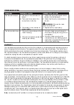
1.  Check the main and branch circuit 

fuses or circuit breakers. 

2.  Check the line wire connections to 

the fan.

WARNING: 

Ensure the main 

power is turned off!
3.  Replace with a new battery.

The fan sounds noisy. 1.  There are loose screws in the 

motor housing. 

2.  The wire connectors inside the 

housing are rattling.

1.  Check to make sure all screws in 

the motor housing are snug (do not 
overtighten).

2.  Check to make sure the wire 

connectors are not rattling against 
each other or against the interior wall 
of the motor assembly.

WARRANTY

The manufacturer warrants this fan to be free from defects in workmanship and material present at
time of shipment from the factory. The warranty terms from the date of purchase. The motor has a 
lifetime warranty and a 2 year warranty for all remaining components. This warranty applies only to 
the original purchaser. The manufacturer agrees to correct such defect at no charge or, at its option, 
replace the ceiling fan with a comparable or superior model.

To obtain warranty service, present a copy of your sales receipt as proof of purchase. All cost of 
removal and reinstallation are the expressed responsibility of the purchaser. Any damage to the 
ceiling fan by accident, misuse or improper installation, or by affi xing accessories not produced by 
this warranty, are at the purchaser’s own responsibility. The manufacturer assumes no responsibility 
whatsoever for fan installation during the lifetime limited warranty. Any service performed by an 
unauthorized person will render the warranty invalid.

Due to varying climate conditions, this warranty does not cover changes in brass fi nish, rusting, 
pitting, tarnishing, corroding or peeling. Brass fi nish fans maintain their beauty when protected from 
varying weather conditions. Any glass provided with this fan is not covered by the warranty.

Any replacement of defective parts for the ceiling fan must be reported within the fi rst year from the 
date of purchase. For the balance of the warranty, call our customer service department at 1-800-643-
0067 for return authorization and shipping instructions so that we may repair or replace the ceiling 
fan. Any fan or parts returned improperly packaged is the sole responsibility of the purchaser. There 
is no further expressed warranty. The manufacturer disclaims any and all implied warranties. The 
duration of any implied warranty which can not be disclaimed is limited to the lifetime limited period as 
specifi ed in our warranty. The manufacturer shall not be liable for incidental, consequential or special 
damages arising at or in connection with product use or performance except as may otherwise be 
accorded by law. This warranty gives you specifi c legal rights and you also have other rights which 
vary from state to state. This warranty supersedes all prior warranties.

Note:

A small amount of “wobble” is normal and should not be considered a defect.

Содержание HIVE Series

Страница 1: ... 643 0067 8 a m 6 p m EST Monday Thursday 8 a m 5 p m EST Friday 1 ATTACH YOUR RECEIPT HERE Serial Number ____________ Purchase Date ____________ R Lowes com harborbreeze EB13135 Harbor Breeze is a registered trademark of LF LLC All Rights Reserved ITEM 0449504 HIVE SERIES CEILING FAN MODEL LP8271LAZ Español p 16 ...

Страница 2: ...rdware Contents 4 Safety Information 4 Preparation 5 Assembly Instructions 6 Remote Control Instructions 8 Wiring Instructions 9 Final Assembly Installation 10 Operating Instructions 12 Care and Maintenance 13 Troubleshooting 14 Warranty 14 Replacement Parts List 15 ...

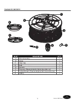
Страница 3: ...PACKAGE CONTENTS B G C D E A F H PART DESCRIPTION QTY A Motor Assembly 1 B Glass 1 C Steel Cap 1 D Bulb 1 E Remote 1 F Receiver Preassembled to Motor Assembly A 1 G Ceiling Bracket Preassembled to Motor Assembly A 1 H Battery 1 ...

Страница 4: ...ould be connected to a grounded conductor power supply If the conductor of a fan is identified as an ungrounded conductor then it should be connected to an ungrounded conductor power supply If the conductor of a fan is identified for equipment grounding then it should be connected to an equipment grounding conductor This device complies with Part 15 of the FCC Rules Operation is subject to the fol...

Страница 5: ...ock do not use this fan with any solid state speed control device WARNING This fan is to be used in dry locations only WARNING Before servicing or cleaning the unit switch power off at the service panel and lock the service disconnecting means to prevent power from being switched on accidentally When the service disconnecting means cannot be locked securely fasten a prominent warning device such a...

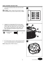
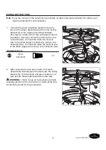
Страница 6: ... ON ON 1 2 Separate the ceiling bracket G from the motor assembly A by loosening the two ceiling bracket screws BB in the slotted holes then removing the two remaining ceiling bracket screws BB in the motor assembly A Retain the screws for later Hardware Used BB Ceiling Bracket Screw x 4 A G BB 2 3 If not done already secure a metal octagonal outlet box not included directly to the building struct...

Страница 7: ...INSTRUCTIONS 4 Securely attach the ceiling bracket G to the outlet box with screws and washers supplied with the outlet box G 4 5 Loop the preassembled ceiling support cable from the motor assembly A over the hook on the ceiling bracket G G A 5 ...

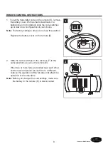
Страница 8: ...ory setting is all up do not use this position Replace the battery cover on the remote E E 1 2 Slide the code switches on the receiver F to the same positions as set on the remote E When two or more fans are located near each other set the receiver remote for each fan to a different code so the operation of this fan does not affect the operation of the other fans Note Before you change the code se...

Страница 9: ...ect the wires with a wire connector AA Connect the white fan receiver wire to the white supply neutral wire using a wire connector AA Connect the black fan receiver wire to the black supply wire using a wire connector AA Hardware Used AA Wire Connector x 3 AA AA 1 2 After connections have been made turn leads upward and carefully push the leads into the ceiling bracket G with the white and green l...

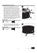
Страница 10: ...slide into the mating slots Rotate the motor assembly A until both ceiling bracket screws BB drop into the slot recesses on the motor assembly A Tighten the ceiling bracket screws BB securely Then install the previously removed ceiling bracket screws BB into the remaining mating holes of the ceiling bracket G to secure the motor assembly A to the ceiling bracket G Hardware Used BB Ceiling Bracket ...

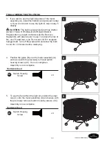
Страница 11: ...duce the risk of fire use 75 watt max type T4 minican JD E11 tungsten halogen bulb Turn off the wall switch and allow the bulb to cool for 10 minutes before relamping D 3 4 Position the glass B onto the motor assembly A and secure with the previously removed switch housing screws CC Do not overtighten Assembly is now complete Hardware Used CC Switch Housing Screw x 4 A B CC 4 5 To use the fan with...

Страница 12: ...IONS 1 Restore electrical power to the outlet box by turning the electricity on at the main fuse box ON ON ON ON ON ON ON ON 1 2 Install the 12 volt battery H into the remote E Press any key on the remote E to make sure the blue light is on E H 2 ...

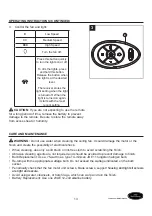
Страница 13: ... from excess heat or humidity E 3 CARE AND MAINTENANCE WARNING Do not use water when cleaning the ceiling fan It could damage the motor or the finish and create the possibility of electrical shock When cleaning use only a soft brush or lint free cloth to avoid scratching the finish Abrasive cleaning agents are not required and should be avoided to prevent damage to finish Bulb Replacement Use a 75...

Страница 14: ...per installation or by affixing accessories not produced by this warranty are at the purchaser s own responsibility The manufacturer assumes no responsibility whatsoever for fan installation during the lifetime limited warranty Any service performed by an unauthorized person will render the warranty invalid Due to varying climate conditions this warranty does not cover changes in brass finish rust...

Страница 15: ...TS For replacement parts call our customer service department at 1 800 643 0067 8 a m 6 p m EST Monday Thursday and 8 a m 5 p m EST Friday PART DESCRIPTION PART A Motor Assembly AMA8271LAZ B Glass AP827115LAZ C Steel Cap P827116LAZ D Bulb PPE11B75 E Remote TR350 F Receiver Unit RECAN67 AA Wire Connector HDWWNUTS4 B E A F D C AA ...

Страница 16: ...lunes a jueves de 8 a m a 6 p m y los viernes de 8 a m a 5 p m hora estándar del Este 16 ADJUNTE SU RECIBO AQUÍ Número de serie ____________ Fecha de compra ____________ Lowes com harborbreeze Harbor Breeze es una marca registrada de LF LLC Todos los derechos reservados ARTÍCULO 0449504 VENTILADOR DE TECHO DE LA SERIE HIVE MODELO LP8271LAZ ...

Страница 17: ...eguridad 19 Preparación 20 Instrucciones de ensamblaje 21 Instrucciones del control remoto 23 Instrucciones de cableado 24 Instrucciones de ensamblaje finales 25 Instrucciones de funcionamiento 27 Cuidado y mantenimiento 28 Solución de problemas 29 Garantía 29 Lista de piezas de repuesto 30 ...

Страница 18: ... C D E A F H PIEZA DESCRIPCIÓN CANT A Ensamble del motor 1 B Vidrio 1 C Tapa de acero 1 D Bombilla 1 E Control remoto 1 F Receptor Preensamblado en el ensamble del motor A 1 G Abrazadera para techo preensamblada en el ensamble del motor A 1 H Batería 1 ...

Страница 19: ...r del ventilador está identificado como conductor con puesta a tierra se le debe conectar a un suministro de electricidad con conductor de puesta a tierra Si el conductor del ventilador está identificado como conductor que no es de puesta a tierra se le debe conectar a un suministro de electricidad con conductor sin puesta a tierra Si el conductor del ventilador está identificado para equipos de p...

Страница 20: ...ara reducir el riesgo de incendios o descargas eléctricas no use este ventilador con dispositivos de control de velocidad de estado sólido ADVERTENCIA Este ventilador es apto solo para lugares secos ADVERTENCIA Antes de reparar o limpiar la unidad corte la energía en el panel de servicio y bloquee los medios de desconexión del servicio a fin de impedir la activación accidental de la energía Cuando...

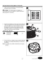
Страница 21: ... techo G del ensamble del motor A aflojando los dos tornillos de la abrazadera para techo BB en los orificios ranurados y luego retirando los dos tornillos de las abrazaderas para techo BB restantes en el ensamble del motor A Guarde los tornillos para más adelante Aditamentos utilizados BB Tornillo de la abrazadera para techo x 4 A G BB 2 3 Si aún no termina asegure la caja de salida octagonal de ...

Страница 22: ...4 Fije bien la abrazadera para techo G a la caja de salida con los tornillos y las arandelas provistas con la caja de salida G 4 5 Enganche el cable de soporte para techo preensamblado desde el ensamble del motor A sobre el gancho en la abrazadera para techo G G A 5 ...

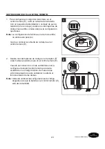
Страница 23: ...a de más arriba no utilice esta posición Vuelva a colocar la cubierta de la batería en el control remoto E E 1 2 Deslice los interruptores de código en el receptor F a las mismas posiciones que en el control remoto E Cuando se colocan dos o más ventiladores cerca configure el receptor control remoto para cada ventilador en un código distinto de manera que el funcionamiento de este ventilador no af...

Страница 24: ...onector de cables AA Conecte el conductor blanco receptor del motor del ventilador al conductor blanco neutro con un conector de cables AA Conecte el conductor negro receptor del motor del ventilador al conductor negro con un conector de cables AA Aditamentos utilizados AA Conector de cables x 3 AA AA 1 2 Una vez realizadas las conexiones gire los conductores hacia arriba y colóquelos con cuidado ...

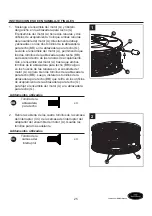
Страница 25: ... el ensamble del motor A hasta que ambos tornillos de la abrazadera para techo BB caigan en los huecos de las ranuras en el ensamble del motor A Apriete bien los tornillos de la abrazadera para techo BB Luego instale los tornillos de la abrazadera para techo BB que retiró en los orificios de acoplamiento de la abrazadera para techo G para fijar el ensamble del motor A a la abrazadera para techo G ...

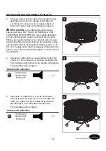
Страница 26: ... utilice una bombilla minican de tungsteno halógena tipo T4 JD E11 de 75 vatios como máximo Apague el interruptor de pared y deje enfriar la bombilla durante 10 minutos antes de cambiarla D 3 4 Coloque el vidrio B en el ensamble del motor A y fíjelo con los tornillos de la carcasa del interruptor CC retirados anteriormente No apriete demasiado El ensamblaje está completo Aditamentos utilizados CC ...

Страница 27: ... eléctrica en la caja de salida volviendo a conectar la electricidad de la caja de fusibles principal ON ON ON ON ON ON ON ON 1 2 Instale la batería de 12 voltios H en el control remoto E Presione cualquier tecla en el control remoto E para asegurarse de que la luz azul se encienda E H 2 ...

Страница 28: ...umedad extremos E 3 CUIDADO Y MANTENIMIENTO ADVERTENCIA No use agua para limpiar el ventilador de techo Puede dañar el motor o el acabado y crea la posibilidad de una descarga eléctrica Use solo una brocha suave o un paño que no produzca pelusas para evitar rayar el acabado al limpiarlo Los agentes limpiadores abrasivos son innecesarios y deben evitarse para no dañar el acabado Reemplazo de la bom...

Страница 29: ...accidente uso indebido o instalación incorrecta o a causa de accesorios de fijación que no están cubiertos por esta garantía será responsabilidad del comprador El fabricante no asume ningún tipo de responsabilidad por la instalación del ventilador durante la garantía limitada de por vida Cualquier servicio realizado por una persona no autorizada invalidará la garantía Debido a las cambiantes condi...

Страница 30: ...e a nuestro Departamento de Servicio al Cliente al 1 800 643 0067 de lunes a jueves de 8 a m a 6 p m y los viernes de 8 00 a m a 5 p m hora estándar del Este PIEZA DESCRIPCIÓN PIEZA A Ensamble del motor AMA8271LAZ B Vidrio AP827115LAZ C Tapa de acero P827116LAZ D Bombilla PPE11B75 E Control remoto TR350 F Unidad receptora RECAN67 AA Conector de cables HDWWNUTS4 B E A F D C AA ...

Отзывы: