

15
Fig. 3a
Fig. 3b
Fig. 3c
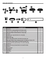
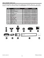
2
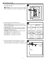
Reverse
Switch
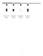
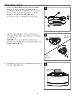
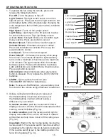
OPERATING INSTRUCTIONS
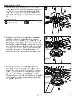
1. To operate the fan using the remote, press and
release the following buttons:
Fan Off
-
Turns the power to fan off.
Light Control:
Tap light control button to turn the
light off and on. Press and hold the light control to dim
and brighten lights while simultaneously changing the
color temperature from 2200K (warm white) to 6500K
(daylight).
High Speed -
Turns on fan at high speed.
Light Delay
-
Light stays on for 60 seconds to allow
for safe exit from room. Tap Light Delay once to
activate.
Note:
Fan light blinks once to confirm Light
Delay is active. Press any button to cancel.
Medium Speed -
Turns on fan at medium speed.
Variable Breeze -
Simulates a breeze in nature.
Press and hold button to activate. Press any fan
speed button to cancel.
Low Speed
-
Turns on fan at low speed.
Home Shield™ -
Simulates occupancy while away
from home. Fan remains off and the light randomly
turns on for a minimum of five times and a maximum
of 20 minutes. The light remains off for 60 minutes
between events. Press and hold button to activate.
Light will blink twice to confirm Home Sheild is active.
Press any button to cancel.
LED indicator
should illuminate when any remote
button is pressed. If not, replace the DC3V, CR2032
batteries.
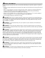
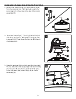
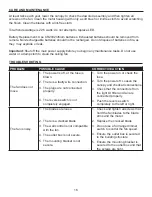
2.
LEARN
- Syncs remote to receiver (see
TROUBLESHOOTING for instructions).
Note:
To access LEARN button, remove battery door
from back of the remote using a flat-head screwdriver.
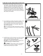
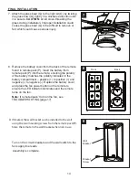
3. Using a ceiling fan will allow you to raise your
thermostat setting in summer and lower your
thermostat setting in winter without feeling a
difference in your comfort.
In warmer weather,
push the reverse switch left to
display a sun icon, which will result in downward airflow
creating a wind chill effect (Fig. 3a).
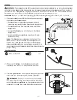
In cooler weather,
push the reverse switch right to
display a snowflake icon, which will result in upward
airflow that can help move hot air off the ceiling area
(Fig. 3b).
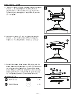
Important:
Wait for the fan to stop before moving the
reverse switch. The reverse switch must be set either
completely left or right for the fan to function correctly.
If the reverse switch is set in the middle position, the
fan will not operate (Fig. 3c).
21
LED Indicator
High Speed
Medium Speed
Low Speed
Fan Off
Light On/Off
Light Delay
Variable Breeze
Home Shield™
3
Battery Compartment
LEARN Button


