background image

8

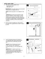
INITIAL INSTALLATION

 8.  Slip downrod (C) into motor assembly yoke, align 

holes and re-install pin (D) and clip (E). Tighten 
set screws in motor assembly yoke and then 
tighten preassembled nuts on the set screws. 
Then, slide yoke cover (H) down until it rests on 
top of motor assembly (I).

8

C

I

H

D

E

Yoke

E

D

Set Screw 

and Nut

Sideview

 9. 

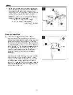
If you decided to cut back the lead wires in Step 8, 
strip 1/2 in. of insulation from end of each
wire -- WHITE, BLUE, PINK, GREY AND RED (if 
applicable). Twist stripped ends of each strand of 
wire within the insulation with pliers (not included). 

Depending on the length of downrod you use, you 
may need to cut the lead wires back to simplify 
the wiring. If you decide to cut back the lead 
wires, it is suggested you do so in the following 
manner:

Take the lead wires and make sure you have 
pulled them all the way through the top of the 
downrod. Start at the TOP of the hanging ball on 
the downrod and measure 8 in. of lead wire, then 
cut the excess wire off with wire cutters (not 
included). 

NOTE:

 If you do 

not

 cut back the lead wires, 

Step 

10 is not necessary and you may proceed to 
Step 11 instead

.

Hanging

Ball

9

C

8 in.

 10. 

10

Содержание CGR60WW3LR

Страница 1: ...18 MODEL CGR60WW3LR ATTACH YOUR RECEIPT HERE Harbor Breeze is a registered trademark of LF LLC All Rights Reserved Questions problems missing parts Before returning to your retailer call our customer...

Страница 2: ...hority to operate the equipment This device complies with Part 15 of the FCC Rules Operation is subject to the following two conditions 1 this device may not cause harmful interference 2 this device m...

Страница 3: ...uce the risk of fire electrical shock or personal injury wire connectors provided with this fan are designed to accept only one 12 gauge house wire and two lead wires from the fan If your house wire i...

Страница 4: ...r Assembly 1 DESCRIPTION PART QUANTITY DESCRIPTION PART QUANTITY J Motor Plate Screw 3 preassembled K Fitter Plate 1 L Fitter Plate Screw 3 preassembled M LED Light Kit 1 N Shade 1 O Blade 3 P Wiring...

Страница 5: ...Required for Assembly not included Electrical Tape Phillips Screwdriver Pliers Safety Glasses Stepladder Wire Strippers and Precision Screwdriver 0 x 2 in Helpful Tools not included AC Tester Light T...

Страница 6: ...wnrod not included Angle style mounting is best suited for angled or vaulted ceilings A longer downrod is sometimes necessary to ensure proper blade clearance 7 ft min 30 in min 3 4 Open End 4 A A ANG...

Страница 7: ...Insert downrod C through canopy F canopy cover G and yoke cover H NOTE Canopy cover G must be turned with the shiny side toward the motor assembly I Then thread wiring P from motor assembly I through...

Страница 8: ...ble Twist stripped ends of each strand of wire within the insulation with pliers not included Depending on the length of downrod you use you may need to cut the lead wires back to simplify the wiring...

Страница 9: ...n is recommended to determine wiring WARNING Using a full range dimmer switch not included to control fan speed will cause a loud humming noise from fan To reduce the risk of fire or electrical shock...

Страница 10: ...ver Q to WHITE supply wire from ceiling Connect RED wire labeled TO MOTOR from remote control receiver Q to RED wire from motor assembly I Connect GRAY wire labeled TO MOTOR from remote control receiv...

Страница 11: ...side of canopy cover G to locate knobs on center ring of canopy cover G Slide canopy cover G up to canopy F aligning knobs on canopy cover G with openings in bottom of canopy F Press up firmly on the...

Страница 12: ...le Repeat for remaining blades O 4 3 3 2 J BB AA I FINAL INSTALLATION Remove one fitter plate screw L from underside of fitter plate K and partially loosen the other two fitter plate screws L 3 Motor...

Страница 13: ...ew L and securely tighten all fitter plate screws L K L 6 M 7 Align slots on shade N with protrusions on underside of fitter plate K Turn shade N clockwise until it no longer turns NOTE Pull down gent...

Страница 14: ...a hammer not included until flush with wall surface Screw bracket screws into plastic anchor The remote control transmitter from remote pack R rests inside the bracket 9 9 Remote Control Bracket Wall...

Страница 15: ...x htm or www earth911 org for more information Remote Control Transmitter Battery 2 IMPORTANT To prevent damage to remote control transmitter remove the battery if not used for long periods Store the...

Страница 16: ...f Carefully loosen canopy and verify that mounting bracket is secure 4 Use a longer downrod or move fan to another location 5 Tighten yoke set screw s securely NOTE A small amount of wobble is normal...

Страница 17: ...limited lifetime warranty Any service performed by an unauthorized person will render the warranty invalid Due to varying climatic conditions this warranty does not cover changes in brass finish rust...

Отзывы: