background image

21

Printed in China

A

E

B

F

C

H

G

K

I

L

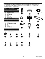
REPLACEMENT PARTS LIST

For replacement parts, call our customer service department at 

1-800-527-1292

, 8:30 a.m. - 5:00 

p.m., CST, Monday - Friday. When ordering parts, please have the Model # or Item # of the fan 
available, which can be found on page 1.

    PART                 DESCRIPTION                


A      Downrod

     B      Canopy  
     C      Mounting Bracket  
     E      Yoke Cover   
     F      Light Kit Fitter    
     G      Blade    


H      Blade Arm

      I      Glass Shade 
     K      Pull Chain Extension
     L      Socket Ring
     M     Motor Screw 
     N      Lock Washer  
     O      Canopy Mounting Screw
     P       Pin
     Q     Clip
     R      Star Washer
     S      Fitter Plate Screw
    AA     Blade Screw 
    BB    Fiber Blade Washer   
    CC    E3 Wire Connector

N

M

O

BB

CC

AA

Q

P

R

S

Содержание BELLEVUE E-BE44ABZ5C

Страница 1: ...ral regulations require ceiling fans with light kits manufactured or imported after January 1 2009 to limit total wattage consumed by the light kit to 190W Therefore this fan is equipped with a wattage limiting device Questions problems missing parts Before returning to your retailer call or contact our customer service department at 1 800 527 1292 8 30 a m 5 00 p m CST Monday Friday ATTACH YOUR R...

Страница 2: ...1999 Hire a qualified electrician or consult a do it yourself wiring handbook available at Lowe s if you are unfamiliar with installing electrical wiring Make sure the installation site you choose allows a minimum clearance of 7 feet from the blades to the floor and at least 30 in from the end of the blades to any obstruction After you install the fan make sure that all connections are secure to p...

Страница 3: ...h this fan are designed to accept only one 12 gauge house wire and two lead wires from the fan If your house wire is larger than 12 gauge or there is more than one house wire to connect to the two fan lead wires consult an electrician for the proper size wire connectors to use To reduce the risk of fire or electrical shock do not use the fan with any solid state speed control device or control fan...

Страница 4: ...teps outlined in this manual Your fan can be installed with or without a downrod Downrod style mounting is best suited for ceilings 8 ft 2 44 m high or higher For taller ceillings you may want to use a longer downrod sold separately than the one provided Angle style mounting is best suited for angled or vaulted ceilings A longer downrod is sometimes necessary to ensure proper blade clearance Close...

Страница 5: ...ock Washer 10 preassembled O Canopy Mounting Screw 4 preassembled P Pin preassembled 1 Q Clip preassembled 1 R Star Washer 4 preassembled S Fitter Plate Screw 3 preassembled PART DESCRIPTION QUANTITY A Downrod 1 B Canopy 1 C Mounting Bracket 1 D Motor Housing 1 E Yoke Cover 1 F Light Kit Fitter 1 G Blade 5 H Blade Arm 5 I Glass Shade 3 J Candelabra Base Bulb 3 A E D B F C H J G K I PACKAGE CONTENT...

Страница 6: ...ring Handbook available at Lowe s and Wire Cutters Bulbs Required included 3 candelabra base 60 watt max bulbs DANGER When using an existing outlet box make sure the outlet box is securely attached to the building structure and can support the full weight of the fan Failure to do this can result in serious injury or death The stability of the outlet box is essential in minimizing wobble and noise ...

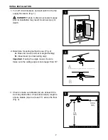
Страница 7: ...1 2 Check to make sure blades G are at least 30 in from any obstruction Check downrod A length to ensure blades G are at least 7 ft above the floor Fig 3 3 ON OFF ON OFF 1 2 Determine mounting method to use Fig 2 A Downrod mount normal or angled ceiling B Closemount normal ceiling only Important If using the angle mount check to make sure the ceiling angle is not steeper than 19 A B 7 ft min 30 in...

Страница 8: ...shers provided with the outlet box Fig 4 NOTE It is very important that you use the proper hardware when installing the mounting bracket C as this will support the fan IMPORTANT If using the angle mount make sure open end of mounting bracket C is installed facing the higher point of the ceiling 4 4 1 Remove motor screws M and lock washers N from underside of motor housing D Note Use opening in fit...

Страница 9: ... downrod A and measure 8 in of lead wire and then cut the excess wire off with wire cutters Fig 4 Note If you do not cut back the lead wires Steps 4 and 5 are not necessary and you may proceed to Step 6 instead Ball A 4 A E B Insert downrod A through canopy B and yoke cover E Thread wires from motor housing D through downrod A Fig 2 2 2 E A D P Q 3 Slip downrod A into motor housing yoke align hole...

Страница 10: ... in this type of installation 1 Install ball end of downrod A into mounting bracket C opening Align slot in ball with tab in mounting bracket C Fig 6 DANGER Failure to align slot in ball with tab may result in serious injury or death A 6 Continue to Wiring instructions on page 12 DOWNROD STYLE FAN MOUNTING If you decided to cut back the lead wires in Step 4 strip 1 2 in of insulation from end of w...

Страница 11: ...will be located in one of the hardware packs Fig 2 Hang motor housing D on the tab on the mounting bracket C using one of the non slotted holes in the canopy B Fig 4 4 D Tab C B CLOSEMOUNT STYLE FAN MOUNTING 2 2 Pull wires through hole in the middle of the canopy B and attach canopy B to motor housing D using the three screws and three lock washers refered to in Step 2 above Fig 3 3 D B 3 4 D 11 ...

Страница 12: ...ring connections as follows NOTE For each wire connection below use one of the wire connectors CC provided making sure to screw wire connector CC on in a clockwise direction 1A FAN AND LIGHT CONTROLLED BY PULL CHAINS Connect BLACK and BLUE wire from fan to BLACK wire from ceiling Connect WHITE wire from fan to WHITE wire from ceiling Connect all GROUND GREEN wires together from fan on downrod A an...

Страница 13: ...full range dimmer switch to control fan speed will cause a loud humming noise from fan To reduce the risk of fire or electrical shock do NOT use a full range dimmer switch to control fan speed Fig 3 3 2 3 1C FAN AND LIGHT CONTROLLED BY TWO WALL SWITCHES WHITE BLACK WALL SWITCH BLACK WALL SWITCH FOR LIGHT GROUND GREEN BARE BLACK BLUE WHITE FROM FAN FAN 120 V Power FROM CEILING GREEN WHITE GREEN WIR...

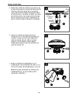
Страница 14: ...g with the one in the middle Fig 2 Repeat with remaining blades G Temporarily lift canopy B to mounting bracket C to determine which two canopy mounting screws O in mounting bracket C align with slotted holes in canopy B and partially loosen these two canopy mounting screws O Remove the other two canopy mounting screws O and star washers R Now lift canopy B to mounting bracket C again aligning slo...

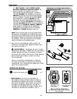
Страница 15: ...s shades I with these same socket rings L Fig 6 Note Do not overtighten socket rings L as glass may crack or break F L I Remove three fitter plate screws S from fitter plate on underside of motor Connect male plug from motor housing D to female plug from light kit fitter F matching up the colors on the male plug with the colors on the female plug for correct fit Fig 4 Make sure that plugs connect ...

Страница 16: ...adaptable remote control sold separately 16 The pull chain labeled FAN has four positions to control fan speed One pull is HIGH two is MEDIUM three is LOW and four turns the fan OFF Fig 1 J Install three candelabra base 60 watt max bulbs J included Fig 7 Important When you need to replace bulbs please allow bulb s and light kit to cool down before touching the bulb s or the light kit 7 8 7 8 OPERA...

Страница 17: ...in your comfort Note Wait for fan to stop before moving the reverse switch 17 The pull chain labeled LIGHT is used to turn the lights ON or OFF Fig 2 2 2 3 3A 3B 3A In warmer weather setting the reverse switch in the LEFT position will result in downward airflow creating a wind chill effect Fig 3A 3B In cooler weather setting the reverse switch in the RIGHT position will result in upward airflow t...

Страница 18: ...ny questions regarding the product please call customer service at 1 800 527 1292 8 30 a m 5 p m CST Monday Friday Warning Before beginning work shut off the power supply to avoid electrical shock PROBLEM POSSIBLE CAUSE CORRECTIVE ACTION Fan does not move 1 Reverse switch not engaged 2 Power is off or fuse is blown 3 Faulty wire connection 4 Plugs not connected properly 1 Push switch firmly either...

Страница 19: ...e a longer downrod A or move fan to another location 6 Tighten yoke set screw s securely 7 Carefully loosen and lower canopy B and verify that set screw on hanging ball is tightened securely Fan operates but lights fail 1 Bulb s not installed correctly 2 Wires in canopy B not wired properly 3 Wall switch to fan is off 4 Plugs not connected properly 5 Light kit is lamped with more than the allowabl...

Страница 20: ...onditions this warranty does not cover changes in brass finish rusting pitting tarnishing corroding or peeling Brass finish fans maintain their beauty when protected from varying weather conditions Any glass provided with this fan is not covered by the warranty Any replacement of defective parts for the ceiling fan must be reported within the first year from the date of purchase For the balance of...

Страница 21: ...e the Model or Item of the fan available which can be found on page 1 PART DESCRIPTION A Downrod B Canopy C Mounting Bracket E Yoke Cover F Light Kit Fitter G Blade H Blade Arm I Glass Shade K Pull Chain Extension L Socket Ring M Motor Screw N Lock Washer O Canopy Mounting Screw P Pin Q Clip R Star Washer S Fitter Plate Screw AA Blade Screw BB Fiber Blade Washer CC E3 Wire Connector N M O BB CC AA...

Страница 22: ...e techo con kit de iluminación fabricados o importados después del 1 de enero de 2009 tengan un límite de vataje total consumido por el kit de iluminación de 190 vatios Por lo tanto este ventilador está equipado con un dispositivo de control de vataje Preguntas problemas piezas faltantes Antes de volver a la tienda llame a nuestro Departamento de Servicio al Cliente al 1 800 527 1292 de lunes a vi...

Страница 23: ...arizado con la instalación del cableado eléctrico contrate a un electricista calificado o consulte un manual de cableado disponible en Lowe s para hacerlo usted mismo Asegúrese de que el sitio de instalación que elija permita una distancia mínima de 2 13 m desde las aspas hasta el piso y de que los extremos de las aspas estén como mínimo a 76 20 cm de cualquier obstáculo Una vez instalado el venti...

Страница 24: ...diseñados para soportar sólo un cable interior de calibre 12 y dos cables conductores del ventilador Si el cable interior es de un calibre superior a 12 o hay más de un cable interior para conectar los dos cables conductores del ventilador pregúntele a un electricista cuál es el tamaño adecuado de los conectores de cables que debe utilizar Para reducir el riesgo de incendios o descargas eléctricas...

Страница 25: ...es se adaptan mejor a sus necesidades antes de comenzar a realizar los pasos detallados en este manual Se puede instalar el ventilador con o sin una varilla El montaje de varilla es mejor para los techos de 2 44 m 8 pies o más de alto Para techos más altos le recomendamos utilizar una varilla más larga se vende por separado que la provista El montaje en ángulo es mejor para los techos en ángulo o ...

Страница 26: ...estrella 4 preensamblada S 3 PIEZA DESCRIPCIÓN CANTIDAD A Varilla 1 B Base 1 C Abrazadera de montaje 1 D Carcasa del motor 1 E Cubierta de la horquilla 1 F Soporte del kit de iluminación 1 G Aspa 5 H Brazo del aspa 5 I Pantalla de vidrio 3 J Bombilla de base candelabro 3 A E D B F C H J G K I CONTENIDO DEL PAQUETE Q P L N M O R S RECORDATORIO IMPORTANTE Debe utilizar las piezas que se incluyen con...

Страница 27: ...ismo disponible en Lowe s y pinzas cortacables Bombillas requeridas se incluyen 3 bombillas de base candelabro de 60 vatios como máximo PELIGRO Si utiliza una caja de salida existente asegúrese de que esté bien sujeta a la estructura del edificio y que pueda sostener el peso del ventilador El incumplimiento de dicho paso podría provocar lesiones graves o la muerte La estabilidad de la caja de sali...

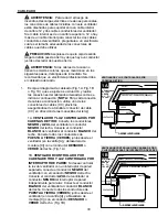
Страница 28: ...e lesiones graves o la muerte Determine el método de instalación que utilizará Fig 2 A Montaje de varilla techos normales o en ángulo B Montaje cerrado sólo para techos normales Importante Si realiza la instalación en ángulo verifique que el ángulo del techo no tenga una inclinación superior a los 19 Verifique que las aspas G estén al menos a 76 20 cm de cualquier obstrucción Verifique el largo de...

Страница 29: ...talados con los tornillos del motor M y las arandelas de seguridad N deseche los topes plásticos del motor Fig 5 Siga las instrucciones de instalación en las páginas 29 a 31 para el estilo de montaje de varilla del ventilador o proceda con las páginas 31 y 32 para el estilo de montaje cerrado del ventilador dependiendo del método de instalación A o B que escoja en el Paso 2 en la página anterior E...

Страница 30: ...la cubierta de la horquilla E hacia abajo hasta que quede sobre la carcasa del motor D Fig 3 Dependiendo del largo de la varilla A que utilice es posible que necesite cortar los cables conductores para simplificar el cableado Si decide cortar los cables conductores se sugiere hacerlo de la siguiente manera Tome los cables conductores y asegúrese de jalarlos completamente a través de la parte super...

Страница 31: ...ale el extremo con la bola de la varilla A en la abertura de la abrazadera de montaje C Alinee la ranura de la bola con la lengüeta en la abrazadera de montaje C Fig 6 PELIGRO Si no alinea la ranura de la bola con la lengüeta pueden producirse lesiones graves o la muerte A 6 Continúe con las instrucciones de Cableado de la página 33 ESTILO DE MONTAJE DE VARILLA DEL VENTILADOR Si decidió cortar los...

Страница 32: ...estarán ubicados en uno de los paquetes de aditamentos Fig 2 Cuelgue la carcasa del motor D en la lengüeta de la abrazadera de montaje C con uno de los orificios sin ranura de la base B Fig 4 4 D Lengüeta C B ESTILO DE MONTAJE CERRADO DEL VENTILADOR 2 2 Pase los cables a través el orificio en el centro de la base B y fije la base B a la carcasa del motor D con los tres tornillos y las tres arandel...

Страница 33: ...a conexión de cables a continuación utilice uno de los conectores de cables CC provistos asegurándose de atornillar el conector de cable CC en dirección de las manecillas del reloj 1A VENTILADOR Y LUZ CONTROLADOS POR CADENAS DE TIRO Conecte los conductores NEGRO y AZUL del ventilador al conductor NEGRO del techo Conecte el conductor BLANCO del ventilador al conductor BLANCO del techo Conecte todos...

Страница 34: ...un regulador de intensidad de rango completo para controlar la velocidad del ventilador provocará un zumbido intenso del ventilador Para reducir el riesgo de incendios o descargas eléctricas NO use un regulador de intensidad de rango completo para controlar la velocidad del ventilador Fig 3 3 2 3 1C BLANCO NEGRO INTERRUPTOR DE PARED NEGRO INTERRUPTOR DE PARED PARA LA LUZ DE PUESTA A TIERRA VERDE D...

Страница 35: ...ro Fig 2 Repita el procedimiento para las aspas restantes G Levante temporalmente la base B hacia la abrazadera de montaje C para determinar cuáles son los dos tornillos de montaje de la base O en la abrazadera de montaje C que se alinean con los orificios ranurados en la base B y afloje parcialmente estos dos tornillos de montaje de la base O Retire los otros dos tornillos de montaje de la base O...

Страница 36: ...los mismos anillos del portalámpara L Fig 6 Nota No apriete demasiado los anillos de los portalámparas L ya que el vidrio podría agrietarse o quebrarse F L I Retire tres tornillos de la placa de soporte S de la placa de soporte en la parte inferior del motor Conecte el enchufe macho de la carcasa del motor D al enchufe hembra del soporte del kit de iluminación F haciendo combinar los colores del e...

Страница 37: ...o FAN VENTILADOR tiene cuatro posiciones para controlar la velocidad del ventilador Jale una vez para la posición HIGH ALTA dos para la posición MEDIUM MEDIA tres para la posición LOW BAJA y cuatro para la posición OFF APAGADO que apaga el ventilador Fig 1 J Instale las tres bombillas de base candelabro de 60 vatios como máximo J incluidas Fig 7 Importante Cuando necesite reemplazar las bombillas ...

Страница 38: ... se detenga antes de mover el interruptor de reversa 38 La cadena de tiro marcada como LIGHT LUZ se utiliza para ENCENDER o APAGAR las luces Fig 2 2 2 3 3A 3B 3A En climas más cálidos la configuración del interruptor de reversa en la posición LEFT IZQUIERDA creará un flujo de aire descendente que generará un efecto de viento refrescante Fig 3A 3B En climas más fríos la configuración del interrupto...

Страница 39: ...elacionadas con el producto llame al Departamento de Servicio al Cliente al 1 800 527 1292 de lunes a viernes de 8 30 a m a 5 p m hora central estándar Advertencia Antes de comenzar cualquier trabajo desconecte el suministro de electricidad para evitar descargas eléctricas PROBLEMA CAUSA POSIBLE ACCIÓN CORRECTIVA El ventilador no se mueve 1 El interruptor de reversa no está activado 2 No hay alime...

Страница 40: ...e B y verifique que el tornillo de fijación de la bola para colgar esté bien apretado El ventilador funciona pero las luces fallan 1 Las bombillas no están bien instaladas 2 Los conductores de la base B no están bien conectados 3 El interruptor de pared del ventilador está apagado 4 Los enchufes no están conectados apropiadamente 5 El kit de iluminación cuenta con lámparas de más de los 190 vatios...

Страница 41: ...cas esta garantía no cubre cambios en el acabado de latón óxido picaduras deslustre corrosión o descascarado Los ventiladores con acabado de latón mantienen su belleza cuando se les protege de las cambiantes condiciones climáticas La garantía no cubre los elementos de vidrio incluidos con este ventilador Cualquier reemplazo de piezas defectuosas para el ventilador de techo debe informarse dentro d...

Страница 42: ... que aparecen en la página 22 PIEZA DESCRIPCIÓN A Varilla B Base C Abrazadera de montaje E Cubierta de la horquilla F Soporte del kit de iluminación G Aspa H Brazo del aspa I Pantalla de vidrio K Extensión para la cadena de tiro L Anillo del portalámpara M Tornillo del motor N Arandela de seguridad O Tornillo de montaje de la base P Pasador Q Sujetador R Arandela de estrella S Tornillo para la pla...

Отзывы: