background image

10

WIRING INSTRUCTIONS

WARNING

To avoid possible electrical shock, be 
sure electricity is turned off at the main fuse 
box before hanging. 

NOTE: If you are not sure if the outlet box is 
grounded, contact a licensed electrician for 
advice, as it must be grounded for safe opertion.


WARNING

Check to see that all connections are 
tight, including ground, and that no bare 
wire is visible at the wire connectors 
except for the ground wire.  Do not 
operate fan until the blades are in place.  
Noise and motor damage could result.

2. After connections have been made, turn leads 

upward and carefully push leads into the outlet 


box, with the white and green leads to one side 


of the box and the black leads toward the 

other side. The wires should be spread apart 
with the grounded conductor and the 


equipment-grounding conductor on one side of 


the outlet box and the ungrounded conductor 


on the other side of the outlet box. (Fig. 2)


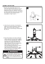
1. 

Connect the green grounding lead from the 

    downrod/hanger ball assembly (D) and the green 
    grounding lead from the hanger bracket (C) to the 
    supply grounding conductor (this may be a bare 
    wire or wire with green colored insulation). 
    Securely connect wires with wire connectors 
    (DD). Securely connect the white fan motor wire 
    to the white supply (neutral) wire using wire 
    connector (DD). Securely connect the black 
     fan motor wire and blue wire to the black 
    supply wire using wire connector (DD). (Fig. 1) 


DD

DD

D

C

1

Green Wire

from Supply

(Ground)

White Wire

from Supply

White Wire

from Fan

Green Wire

from Hanger

Bracket (Ground)

Green Wire

from Hanger

Ball (Ground)

Listed

Outlet Box

Household

Supply

Black Wire

from Supply

Blue Wire

from Fan

Black Wire

from Fan

Hardware Used

DD

x 3

Wire
Connectors

2

Green Wire

from Supply

(Ground)

White Wire

from Supply

White Wire

from Fan

Green Wire

from Hanger

Bracket (Ground)

Green Wire

from Hanger

Ball (Ground)

Listed

Outlet Box

Household

Supply

Black Wire

from Supply

Blue Wire

from Fan

Black Wire

from Fan
Содержание 0331104

Страница 1: ...service department at 1 800 643 0067 8 a m 6 p m EST Monday Thursday and 8 a m 5 p m EST Friday Espa ol p 22 ITEM 0331104 MODEL LP8055LAZ SOUTHLAKE CEILING FAN Harbor Breeze is a registered trademark...

Страница 2: ...n Operating Instructions Blade Balancing Installation Instructions Care And Maintenance Troubleshooting Warranty Replacement Parts List 2 COMPONENTE ESPECIFICACIONES A B C D E F G H I J K Motor Assemb...

Страница 3: ...nt the fan from falling Instructions for supply connections conductor of a fan identified as grounded conductor to be connected to a grounded conductor of power supply conductor of a fan identified fo...

Страница 4: ...4 SAFETY INFORMATION Continued The net weight of this fan is 22 24 lbs 10 09 kg This fan is to be used in dry or damp locations only WARNING...

Страница 5: ...ight Fitter Assembly 1 C Hanger Bracket 1 D Downrod Hanger Ball Assembly 1 E Ceiling Canopy 1 F Canopy Screw Cover 1 G Motor Coupling Cover 1 H Blade Holder Arm 5 I Blade 5 J Bulb 1 PART DESCRIPTION Q...

Страница 6: ...ontents list and diagram above If any part is missing or damaged do not attempt to assemble the product Contact customer service for replacement parts Estimated Assembly Time 60 minutes Tools Required...

Страница 7: ...l assembly D Fig 2 1 2 WARNING It is critical that the clevis pin in the downrod support is properly installed and the set screws is securely tightened Failure to do so could result in the fan falling...

Страница 8: ...sembly D through the two holes in the downrod and align the hanger ball so the pin is captured in the groove in the top of the hanger ball Pull the hanger ball up tight against the pin Securely tighte...

Страница 9: ...not pinch wires between the hanger ball assembly and the hanger bracket C D 2 Carefully lift the fan and seat the downrod hanger ball assembly D on the hanger bracket C that was just attached to the...

Страница 10: ...on the other side of the outlet box Fig 2 1 Connect the green grounding lead from the downrod hanger ball assembly D and the green grounding lead from the hanger bracket C to the supply grounding con...

Страница 11: ...ting key slot over shoulder screw in hanger bracket C Tighten shoulder screw Fully assemble and tighten second shoulder screw that was previously removed Fig 1 1 E 2 Securely attach and tighten the ca...

Страница 12: ...duce the risk of personal injury do not bend the blade holders when install ing balancing the blades or cleaning the fan Do not insert foreign objects in between the rotating blades 3 Attach blade hol...

Страница 13: ...e two single pin down light connector from the light fitter assembly B to the socket plate assembly K Fig 3 4 Remove one of the three screws in the light fitter assembly B Slightly loosen the remainin...

Страница 14: ...ockwise onto the socket plate assembly K Don t overtighten or force it Fig 6 6 L 5 Install bulb J Fig 5 5 J CAUTION Bulb is pressurized and may shatter DO NOT TOUCH BULB WITH BARE HANDS Fingerprints m...

Страница 15: ...h Position Clockwise Counterclockwise Left Right Reverse Switch Information PULL CHAIN OPERATING INSTRUCTIONS Continued EE Hardware Used EE Fan Chain Coupler GG Light Kit Chain Coupler x 1 x 1 2 Insta...

Страница 16: ...CTIONS Continued 16 Hardware Used GG Light Kit Chain Coupler x 1 5 Check the operation of the light by gently pulling on the light kit chain coupler GG Fig 5 1st Pull 2nd Pull On Off Light Kit Pull Ch...

Страница 17: ...I install the balancing clip in the balance kit FF to the top edge of the blade I near the blade holder arm H Fig 2 Start the fan and notice wobble Stop the fan and move the balancing clip in the bala...

Страница 18: ...FK FDQ ZDUS DQG UXLQ WKH ILQLVK CARE AND MAINTENANCE Fan will not start 1 Fuse or circuit breaker blown 2 Loose power line connections to the fan or loose switch wire connections in the switch housing...

Страница 19: ...and result in a smoother operation For example exchange blades in positions 1 and 3 or 1 and 4 If this does not improve wobble exchange 2 and 4 or 2 and 5 1 If possible consider using a longer downrod...

Страница 20: ...arnishing corroding or peeling Brass finish fans maintain their beauty when protected from varying weather conditions Any glass provided with this fan is not covered by the warranty Any replacement of...

Страница 21: ...100 Socket Plate Assembly AP807205WH Glass Wire Connector Balance Kit Washer Head Screw Fan Chain Coupler P807206OP Screw HDWBH8005SS HDWBM8005SS HDWWNUTS4 ALP000002LAZ ALP000001LAZ LBALKT Light Kit C...

Страница 22: ...C Todos los derechos reservados Adjuntar su recibo AQU N mero de serie Fecha de Compra Preguntas problemas piezas faltantes Antes de volver a la tienda llame a nuestro Departamento de Servicio al Clie...

Страница 23: ...e del soporte de iluminaci n Cubierta para los tornillo de la base COMPONENTE ESPECIFICACIONES L Vidrio Informaci n de seguridad Contenido del paquete Aditamentos Preparaci n Instrucciones de ensambla...

Страница 24: ...dificio La caja de salida y su soporte deben ser capaces de sostener el peso del ventilador en movimiento como m nimo 15 88 kg NO use una caja de salida de pl stico Una vez instalado el ventilador ase...

Страница 25: ...PARA SOPORTE DE VENTILADOR y use los tornillos de montaje que se proporcionan con la caja de salida La mayor a de las cajas de salida que se usan com nmente para sostener ensambles de iluminaci n no...

Страница 26: ...placa del portal mpara Brazo de soporte del aspa Cubierta para el acoplador del motor Escudo del techo Ensamble de la bola para colgar varilla Abrazadera para colgar Ensamble del soporte de iluminaci...

Страница 27: ...r todas las piezas Compare las piezas con la lista del contenido del paquete y el diagrama anterior No intente ensamblar el producto si falta alguna pieza o si stas est n da adas P ngase en contacto c...

Страница 28: ...g 2 1 2 3 D A 3 Haga pasar la varilla del ensamble de la bola para colgar varilla D por el soporte para varilla en la parte superior del ensamble de motor A Instale el pasador de horquilla del ensambl...

Страница 29: ...5 Vuelva a instalar la bola para colgar en el ensamble de la bola para colgar varilla D haciendo pasar los tres conductores de 1 37 m a trav s de la bola para colgar Coloque el pasador del ensamble de...

Страница 30: ...star bien asegurada La abrazadera para colgar debe estar bien asentada contra la caja de salida Si la caja de salida est empotrada retire el panel hasta que la abrazadera haga contacto con la caja Si...

Страница 31: ...e de cortar la alimentaci n el ctrica de la caja de fusibles principal antes de colgar el ventilador ADVERTENCIA NOTA Si no est seguro de si la caja de salida tiene conexi n a tierra pida consejo a un...

Страница 32: ...ble descarga el ctrica o incendio aseg rese de colocar los cables el ctricos completamente dentro de la carcasa de la base y de no apretarlos entre la carcasa y el techo ADVERTENCIA 2 Coloque y ajuste...

Страница 33: ...las aspas y vuelva a asegurarlos si es necesario 3 Fije los soportes de las aspas H al eje del motor A con los tornillos de AA Fig 3 Para reducir el riesgo de lesiones personales no doble los soporte...

Страница 34: ...ctores de luz hacia abajo de clavija simple del ensamble del soporte de iluminaci n B al ensamble de la placa del portal mpara K Fig 3 4 Retire uno de los tres tornillos del ensamble del soporte de il...

Страница 35: ...ilares con alcohol antes de usar la bombilla Para disminuir el riesgo de incendios utilice una bombilla minican tipo T4 JD E11 de tungsteno hal gena de 100 vatios como m ximo Apague el interruptor de...

Страница 36: ...or jalando suavemente del acoplador de la cadena del ventilador EE Fig 3 1 tirada 2 tirada 3 tirada 4 tirada Alta Apagado Baja Media Secuencia de funcionamiento de la cadena del tirador 4 Si desea que...

Страница 37: ...a cadena del kit de iluminaci n Aditamentos utilizados GG x 1 GG 5 5 Verifique el funcionamiento de la luz jalando suavemente del acoplados de la cadena del kit de iluminaci n GG Fig 5 1 tirada 1 tira...

Страница 38: ...tale en dicha aspa I el sujetador de equilibrio del kit de equilibrio FF en el borde superior del aspa I cerca de su brazo de soporte H Fig 2 Haga funcionar el ventilador y detecte el tambaleo Detenga...

Страница 39: ...aspas no est n sujetas al ventilador 2 Hay tornillos flojos en la carcasa del motor 1 Fije las aspas al ventilador antes de ponerlo en funcionamiento 1 Se fundi un fusible o el interruptor de circuito...

Страница 40: ...e del motor est n flojos 1 Fije bien ambos tornillos de fijaci n y sus tuercas al soporte de la varilla 2 Apriete el tornillo de fijaci n en el ensamble de la bola para colgar varilla 3 Compruebe que...

Страница 41: ...n o descascaramiento Los ventiladores con acabado de lat n mantienen su belleza cuando se les protege de las cambiantes condiciones atmosf ricas La garant a no cubre los elementos de vidrio incluidos...

Страница 42: ...Conectores de cable Kit de equilibrio Tornillo con cabeza de arandela Acoplador de la cadena del ventilador P807206OP Tornillo de HDWBH8005SS HDWBM8005SS HDWWNUTS4 ALP000002LAZ ALP000001LAZ LBALKT Ac...

Отзывы: