background image

G

G

Tornillo

21

22

INSTRUCCIONES DE ENSAMBLAJE

INSTRUCCIONES DE ENSAMBLAJE

Aditamentos utilizados

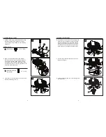
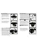
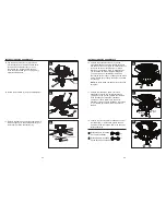
7.  Fije un aspa (F) a una abrazadera del aspa (E) 

utilizando los tornillos para aspa (EE). Apriete 

firmemente todos los tornillos del aspa (EE). 

Repita los mismos pasos para el resto de las 

aspas (F).

10. Inserte los conductores desde el motor (B) 

a través del orificio central en la carcasa del 

interruptor (G). Fije la cubierta de la carcasa 

del interruptor (G) a la placa de la carcasa del 

interruptor (C). Alinee los orificios del chavetero 

y gire para bloquear. Coloque nuevamente el 

tornillo que retiró antes (paso 9, página 8)  

y apriete los tres tornillos.

8. 

Alinee los orificios entre el soporte de aspa (E) y el 

motor (B). Instale el ensamble de aspa en el motor 

(B) usando los tornillos del soporte de aspa con las 

arandelas (FF). Apriete con firmeza cada tornillo 

del soporte de aspa con la arandela (FF). Repita 

los pasos para ensamblar las aspas restantes.

11. Retire los tornillos preensamblados de la 

carcasa del interruptor (G).

F

E

EE

7

Tornillo

G

C

Orificio del 

chavetero

10

E

E

B

B

FF

FF

8

11

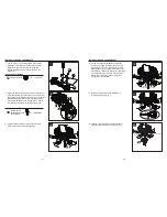
9.  Suelte los dos tornillos y retire un tornillo de la 

placa de la carcasa del interruptor (C).

C

Tornillo

9

Aditamentos utilizados

EE

Tornillo para aspa                x 15 + 1 adicional

FF

Tornillo para la 

abrazadera de aspa 

con arandela

10 + 1 adicionales

12. Conecte el enchufe macho del ventilador al 

enchufe hembra del kit de iluminación (H).

Conector 

macho

H

Conector hembra

12

Página 8

Página 9

Содержание 00723

Страница 1: ...eeze is a registered trademark of LF LLC All Rights Reserved Questions problems missing parts Before returning to your retailer call our customer service department at 1 800 643 0067 8 a m 6 p m EST Monday Thursday 8 a m 5 p m EST Friday EB16372 ATTACH YOUR RECEIPT HERE UL LSD52 COVER Page 1 Page 12 ...

Страница 2: ...unding conductor on one side of the outlet box and the ungrounded conductor on the other side of the outlet box Splices after being made should be turned upward and pushed carefully up into the outlet box All set screws must be checked and retightened during and before installation The net weight of this fan including the light kit is 26 4 lbs ELECTRIC SHOCK HAZARD To reduce the risk of electric s...

Страница 3: ... tape pliers wire cutters wire strippers PACKAGE CONTENTS PART DESCRIPTION QUANTITY A Mounting Plate 1 B Motor 1 C Switch Housing Plate preassembled to motor B 1 D Motor Housing 1 E Blade Bracket 5 F Blade 5 G Switch Housing 1 H Light Kit 1 I Glass Bowl 1 J Bowl Cap preassembled to light kit H 1 K Finial preassembled to light kit H 1 L Bulb 2 B A C F G H D I J K L E CC DD BB EE FF AA Wire Connecto...

Страница 4: ...or bracket so the threaded studs on the mounting plate A protrude through the slots in the motor bracket Securely tighten the three lock nuts BB onto the threaded studs NOTE Lightly shake the motor bracket to ensure the assembly is tight 2 Carefully lift the motor B and engage the slot in the preassembled bracket with the hook on the mounting plate A so it is securely suspended 3 Connect the suppl...

Страница 5: ...ten all three screws 8 Align the holes between the blade bracket E and motor B Install the blade assembly to the motor B using blade bracket screws with washers FF Tighten each blade bracket screw with washer FF securely Repeat for the remaining blade assemblies 11 Remove the preassembled screws from the switch housing G F E EE 7 Screw Keyslot hole G C 10 E E B B FF FF 8 11 9 Loosen two screws and...

Страница 6: ...ngled in light kit H socket Thread light kit pull chain through center hole of glass bowl I 17 Place previously removed rubber washer and hex nut Step 15 page 10 onto the pipe and securely tighten Pass the fan pull chain through the side hole of the bowl cap J then place bowl cap J and finial K over pipe and securely tighten NOTE Two people are recommended for this step ASSEMBLY INSTRUCTIONS Rubbe...

Страница 7: ...G F Blade 108002 505975 I Glass bowl 991300 0544FF L Bulb 990317 0053FD WARRANTY REPLACEMENT PARTS LIST The manufacturer warrants this fan to be free from defects in workmanship and material present at time of shipment from the factory for lifetime limited from the date of purchase This warranty applies only to the original purchaser The manufacturer agrees to correct such defect at no charge or a...

Страница 8: ...a marca registrada de LF LLC Todos los derechos reservados Preguntas problemas piezas faltantes Antes de volver a la tienda llame a nuestro Departamento de Servicio al Cliente al 1 800 643 0067 de lunes a jueves de 8 a m a 6 p m y los viernes de 8 a m a 5 p m hora estándar del Este ADJUNTE SU RECIBO AQUÍ UL LSD52 ...

Страница 9: ...ierra hacia el otro Después de hacer los empalmes se deben girar hacia arriba y empujar con cuidado para introducirlos en la caja de salida Todos los tornillos prisioneros se deben revisar y volver a apretar antes y durante la instalación El peso neto de este ventilador incluido el kit de iluminación es 11 97 kg PELIGRO DE DESCARGA ELÉCTRICA para reducir el riesgo de descargas eléctricas no use es...

Страница 10: ...IEZA DESCRIPCIÓN CANTIDAD A Placa de montaje 1 B Motor 1 C Placa de la carcasa del interruptor preensamblada en el motor B 1 D Carcasa del motor 1 E Abrazadera para aspa 5 F Aspa 5 G Carcasa del interruptor 1 H Kit de iluminación 1 I Pantalla de vidrio 1 J Tapa de la pantalla preensamblada en el kit de iluminación H 1 K Remate preensamblado en el kit de iluminación H 1 L Bombilla 2 B A C F G H D I...

Страница 11: ...tantes roscados en la placa de montaje A sobresalgan a través de las ranuras en la abrazadera del motor Apriete con firmeza las tres contratuercas BB en los montantes roscados NOTA Agite ligeramente el soporte del motor para asegurarse de que el ensamble esté apretado 2 Levante cuidadosamente el motor B y calce la ranura en el soporte preensamblado con el gancho en la placa de montaje A para que q...

Страница 12: ...res tornillos 8 Alinee los orificios entre el soporte de aspa E y el motor B Instale el ensamble de aspa en el motor B usando los tornillos del soporte de aspa con las arandelas FF Apriete con firmeza cada tornillo del soporte de aspa con la arandela FF Repita los pasos para ensamblar las aspas restantes 11 Retire los tornillos preensamblados de la carcasa del interruptor G F E EE 7 Tornillo G C O...

Страница 13: ...de tiro del kit de iluminación por el orificio central de la pantalla de vidrio I 17 Coloque la arandela de goma y la tuerca hexagonal que retiró con anterioridad paso 15 página 10 en el tubo y apriete con firmeza Pase la cadena del tirador del ventilador a través del orificio lateral en la tapa de la pantalla J luego coloque la tapa de la pantalla J y el remate K sobre el tubo y apriete con firme...

Страница 14: ...anecillas del reloj crea un flujo de aire ascendente que mueve el aire caliente desde el techo hacia la parte central de la habitación Presione el interruptor hacia la DERECHA y verá el ícono de un copo de nieve Ícono de sol Ícono de copo de nieve PIEZA DESCRIPCIÓN PIEZA E Abrazadera para aspa 104000 0316NG F Aspa 108002 505975 I Pantalla de vidrio 991300 0544FF L Bombilla 990317 0053FD GARANTÍA L...

Отзывы: