background image

3

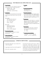
1. Power Supply

This color monitor shall maintain the specified

per formance in the range described below.

Frequency : 47Hz 

63Hz 

Voltage : 90VAC-264VAC 
Consumption :  Less than 70Watts

2. Input Signal 

The referenced video controller used for adjustment

and test will guarantee the performance described
below.

Video signals 

Red, Green, Blue analog input

150

termination to ground

Level  :  0 to 2.4Vp-p
Polarity  :  Positive

Sync signals 

Separate H/V sync input

10k termination to ground 
Level : TTL level 
Polarity : Positive or Negative                     

3. Horizontal Def lection 

Scanning Frequency  :  Nominal (15-17.5kHz)              

Retrace period  :  

11.5us

4. Vertical Deflection

Scanning Frequency  :  Nominal (50-65Hz)                   

Retrace period  : 

900us

5. Linearity 

±

5%

6. Picture Size Regulation

Static Regulation 2%

Dynamic Regulation 1.5%

7. Geometric Distortion

It is acceptable that pincushion, trapezoid, paralle- 
logram, barrel distortion, out of orthogonality and 
various waves can appear all together. If the data 
area parameter remains within the limits of  2%.

8. Degaussing

This color monitor shall employ an  automatic

degaussing  circuit, The  degaussing  sequence 
shall be self activated at the time of switch-on. 
After a degaussing cycle, the demagnetizing circuit 
shall recover.

9. High Voltage

This color monitor shall employ an X-radiation

shut-down protection with internal circulitry.

13"  :  26KV
19"  :  27KV

10. Environmental Conditions

Temperature  :  10 ~ 55

(Operating)

Humidity  :  10 ~ 90%, no condensation

1. Apply line AC,90V-264V, in your locality to the 

monitor through W801.

2.  Apply signal source to the monitor through W301.

3.  Set up user ad justable controls.

All  controls  are  preset  at  the  factory  for  optimum
performance.  If  adjustment  is  necessary  to  suit
program  material,  most  adjustments  can  be  made
using  only  the  controls  on  the  remove  VR  PCB.
Other  controls  in  the  monitor  should  be  adjusted
only if those controls have been tampered with or if
major repairs were necessary on the monitor.

PERFORMANCE AND OPERATING DATA

OPERATING INSTRUTIONS

Содержание Vision Pro MTG-1901CN

Страница 1: ... MTG XX01 SERIES 13 19 CGA OPEN FRAME COLOR MONITORS 19 49 1329 VP2 13 49 1345 VP2 MTG XXO1 Publication A Issue 1 Information in this publication current as of June 2003 Information subject to change as display technology advances ...

Страница 2: ...sion NEVER attempt to modify these circuits 2 Periodically check the high voltage with a reliably calibrated meter for values not in excess of manufacture recommendations See High Voltage Shut down Circuit page 4 for further details CRT Warning All picture tubes used in Happ Controls monitors are quipped with an integral implosion protection system The picture tube is however a highly evacuated co...

Страница 3: ...nality and various waves can appear all together If the data area parameter remains within the limits of 2 8 Degaussing This color monitor shall employ an automatic degaussing circuit The degaussing sequence shall be self activated at the time of switch on After a degaussing cycle the demagnetizing circuit shall recover 9 High Voltage This color monitor shall employ an X radiation shut down protec...

Страница 4: ...radiation in accordance with US DHHS rules 21 CFR subchapter J applicable at date of manufacture A high voltage shut down circuit as shown below guarantees horizontal oscillation shut down A flyback pulse is generated at pin 10 of flyback trans former This pulse is fed through a resistive divider network to pin 13 of I301 The voltage appearing on pin 13 is compared with a precise internal voltage ...

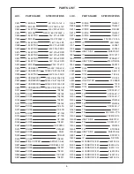
Страница 5: ...F RSS C344 C ELECTRO 16V 220uF RSS C345 C MYLAR 100V 0 1uF J C346 C MYLAR 100V 0 1uF J LOC PARTS NAME SPECIFICATIONS C348 C ELECTRO 16V 100uF RSS C349 C CERAMIC B 50V 680pF K C350 C CERAMIC B 50V 680pF K C351 C CERAMIC B 50V 680pF K C352 C CERAMIC B 50V 680pF K C353 C CERAMIC B 50V 680pF K C354 C CERAMIC B 50V 680pF K C357 C CERAMIC B 50V 680pF K C360 C ELECTRO 25V 1000uF RSS C362 C ELECTRO 35V 47...

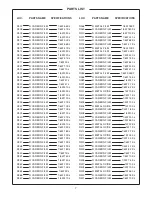
Страница 6: ...C D401 DIODE PS156R D402 DIODE RH4F D403 DIODE RU4AM D405 DIODE 1N4937 D407 WIRE COPPER AWG22 1 0 65 D801 DIODE D3SBA60 4100 D802 DIODE 1N4937 D804 DIODE 1N4937 D805 DIODE UZ 7 5B D807 DIODE 1N4937 LOC PARTS NAME SPECIFICATIONS D808 DIODE 1N4937 D809 DIODE 1N4937 D810 DIODE RU3AM D813 DIODE 1N4937 D814 DIODE 1N4937 F801 FUSE 218 250V 3 15A I201 IC LM1205N I301 IC LA7851 I302 IC LA7833 I302A HEAT S...

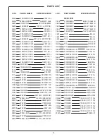
Страница 7: ...LM 1 6W 10K J R364 R CARBON FILM 1 6W 2K J R366 R CARBON FILM 1 6W 22K J R367 R CARBON FILM 1 6W 470 J LOC PARTS NAME SPECIFICATIONS R368 R METAL FILM 1 6W 18K F R369 R CARBON FILM 1 6W 180K J R370 R CARBON FILM 1 6W 120K J R371 R CARBON FILM 1 6W 330 J R372 R CARBON FILM 1 6W 68K J R376 R CARBON FILM 1 6W 4 7K J R378 R METAL FILM 1 6W 10K F R379 R METAL FILM 1 6W 3 3K F R380 R CARBON FILM 1 4W 43...

Страница 8: ... W510A WAFER 5267 04A W801 WAFER YFW800 02 W802 WIRE LEAD UL 1015 18 BK 150 W803 WAFER YFW600 02 W804 WIRE LEAD UL 1015 18 BK 150 LOC PARTS NAME SPECIFICATIONS NECK PCB C514 C CERAMIC B 2KV 1000pF K C551 C CERAMIC B 50V 150pF K C552 C CERAMIC B 50V 150pF K C553 C CERAMIC B 50V 150pF K C560 C ELECTRO 16V 100uF RSS L551 COIL 82uH J L552 COIL 82uH J L553 COIL 82uH J Q551 TR KTC3229 Q552 TR KTC3229 Q5...

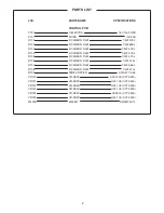
Страница 9: ...BON FILM 1 4W 4 7K J R705 R CARBON FILM 1 4W 4 7K J R706 R CARBON FILM 1 4W 330 J R707 R CARBON FILM 1 4W 5 6K J R708 R CARBON FILM 1 4W 470 J R709 WIRE COPPER AWG22 1 0 65 VR720 VR SEMI H09 200K CCT 092A VR721 VR SEMI H09 10K CCT 092A VR722 VR SEMI H09 10K CCT 092A VR723 VR SEMI H09 10K CCT 092A VR724 VR SEMI H09 500 CCT 092A VR725 VR SEMI H09 10K CCT 092A W401B WAFER SMAW250 12 PARTS LIST ...

Страница 10: ......

Страница 11: ......

Отзывы: