

Function
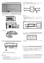
Connection diagram
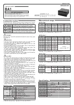
Dimensions and pannel cutout
Select decimal position
Repair and inspection
After Service
█
Power supply connection
Digital
Panelmeter
Twin shield cable
Input
<Figure 1>
<Figure 2>
Input
Digital
Panelmeter
Motive power
●
Please use the backside terminal for decimal position selection.
●
When turning on 1.999 decimal point, please connect to terminal number 7
(COM) and number 4 terminal which are common terminals of decimal
point.
• Please keep the device under the 60% humidity within the temperature -10
to +70. Please get rid of the dust when using it in the dusty places.
(The machine's life is shortened due to high temperature of components in
the device).
• Please be cautious not to touch thinner and volatile oil since this
instrument's case is molded plastic.
This product is released out after production, testing, and examination through a
strict quality control. If it has broken down, please contact the dealer or our
headquarters directly.(Please send the defective product with the detailed
information about it.)
Unit
: ㎜
•
For input signal (direct voltage or 4-20 mA d.c.. 1-5 V d.c.), please connect
to terminal number 8 and terminal number 10.
• For the connection wire use two pieces of shield wire and connect shield to
terminal number 8.
(Refer to figure 2)
•Connect power to the power terminal.
•
Connect "+" to number 1 terminal and "-" to number 2 terminal for power 5
V DC. Use the power within
±
5 % of 5 V DC.
•
Even using the prevention device against noise depending on the types, it
is very difficult to equip the absolute prevention device to such a small
equipment like a digital panelmeter.
█
Input's connection
※ When using more than one BA1, please use separate power supply.
Please be cautious that
②
and
⑧
terminals are internally short.
<Figure 1> In case you use S.M.P.S.
This noise problem does not happen with all S.M.P.S, but if the requirements are not
met, you can see the effect by adding the condenser to the driving power source, as
below.
●
Dimensions
●
Panel cutout
Input signal
Voltage, current, current loop (4 - 20
㎃
d.c., 1 - 5 V d.c.)
A/D conversion type Duplex integral type
Sampling cycle
300
㎳
Response speed
Approx. 2 sec (max range)
Max displayable digit
±
1999
Displaying part
7 segments LED
Decimal point indication 10¹, 10² and 10³ indication by the backside terminal connection
Polarity indication Display “-” automatically when input signal is opposite.
Indication when
range is exceeded Indicate with
Indication when
range is short
Indicate with
DC signal input