


Model
Low TPR-3SL 040L-EP TPR-3SL 055L-EP TPR-3SL 070L-EP TPR-3SL 090L-EP TPR-3SL 130L-EP TPR-3SL 160L-EP
High TPR-3SL 040H-EP TPR-3SL 055H-EP TPR-3SL 070H-EP TPR-3SL 090H-EP TPR-3SL 130H-EP TPR-3SL 160H-EP
Power supply
voltage
Low
100
-
240 V a.c.
High
100
-
440 V a.c.
Circuit input power
100
-
240 V a.c. 18 W
※ Rated current 130 A, 160 A specification Separate input of FAN power
-
24 V d.c. 10 W
Power frequency
50/60 Hz (Dual usage)
Rated current
40 A
55 A
70 A
90 A
130 A
160 A
Applying load
Resistive load
Current input
4
-
20 mA d.c. (Impedance : 100 Ω)
Control method
Phase control, Fixed Cycle control, Variable Cycle control
Movement type
SOFT START, SOFT UP/DOWN
Output voltage
More than 98 % of the power supply voltage (In case of maximum current input)
Cooling method
Forced cooling
Display method
Display by LED
Insulation resistance
Min 100 MΩ (Base on 500 V d.c. mega)
Output control range
0 ~ 100 %
Dielectric strength
3000 V a.c. 50/60 Hz for 1 min
Line noise
Noise by noise simulator (2,500 V)
Ambient temperature &
Humidity
0 ~ 40 ℃(Without Condensation), 30 ~ 85 % RH
Storage temperature
-
25 ~ 70 ℃
Approval
Weight(g)
4,324
9,194
9,288
Thyristor Power Regulator
TPR-3SL-EP
Thank you for purchasing Hanyoung Nux products. Please read the
instruction manual carefully before using this product, and use the product
correctly. Also, please keep this manual where you can view it any time.
MB0602KE201103
INSTRUCTION MANUAL
▍Safety information
DANGER
Indicates an imminently hazardous situation which, if not avoided, will result in death or serious injury
WARNING
Indicates a potentially hazardous situation which, if not avoided, could result in death or serious injury
CAUTION
Indicates a potentially hazardous situation which, if not avoided, may result in minor injury or property damage
• If there is a possibility that a malfunction or abnormality of this
product may lead to a serious accident, install an appropriate
protection circuit on the outside.
• Any use of the product other than those specified by the
manufacturer may result in personal injury or property damage.
• Since this product is not designed as a safety device if it is used
with systems, machines and equipment that could lead to a risk
of life or property damage, please implement safety devices and
protections for both lives and the applications and plan for
preventing accidents.
• Please supply the rated power voltage, in order to prevent
product breakdowns or malfunctions.
• To prevent electric shocks and malfunctions, do not supply the
power until the wiring is completed.
• Never disassemble, modify, process, improve or repair this
product, as it may cause abnormal operations, electric shocks or fires.
• Please disassemble the product after turning OFF the power.
Failure to do so may result in electric shocks, product abnormal
operations or malfunctions.
• Since the product operating environment influences the product
performance and expected life span, please avoid using in the
following places.
· a place where humidity is high and air flow is inappropriate.
· a place where dust or impurity accumulates, ambient temperature is
high and vibration level is high.
· a place where corrosive gases
(such as harmful gases, ammonia, etc.) and flammable gases occur.
· a place where there is direct vibration and a large physical impact
to the product.
· a place where there is water, oil, chemicals, steam, dust, salt, iron or
others (Contamination class 1 or 2).
· a place where excessive amounts of inductive interference and
electrostatic and magnetic noise occur.
· a place where heat accumulation occurs due to direct sunlight or
radiant heat.
• Please do not wipe the product with organic solvents such as alcohol,
benzene, etc. (use neutral detergents).
• When water enters, short circuit or fire may occur, so please inspect
the product carefully.
• Please connect the product and other units after turning off all the
power of the product, instruments and units.
• Please make sure that the thyristor power regulator (TPR) is installed vertically.
• Please install the product inside of the control panel and install an
exhaust fan onto the top of the control panel.
• Pay attention to the edge of heat sink which is sharp.
• Please close the cover after installation in the place in which there is a cover.
• The external circuit connected with the product should be connected
by an insulated circuit more than basic insulation.
• The temperature of the body and the heat sink may be extremely high
when electric current is applied, which may cause burns.
To prevent electric shock while it is running, put to earth with the fixed
screw of the unit and do not touch the heat sink since it is very hot. Do
not touch or contact the input/output terminals because they cause
electric shock.
Please read the safety information carefully before the use, and use the product correctly. The alerts declared in the
manual are classified into Danger, Warning and Caution according to their importance
DANGER
WARNING
CAUTION
28, Gilpa-ro 71beon-gil,
Michuhol-gu, Incheon, Korea
TEL : +82-32-876-4697
http://www.hanyoungnux.com
HANYOUNGNUX CO.,LTD
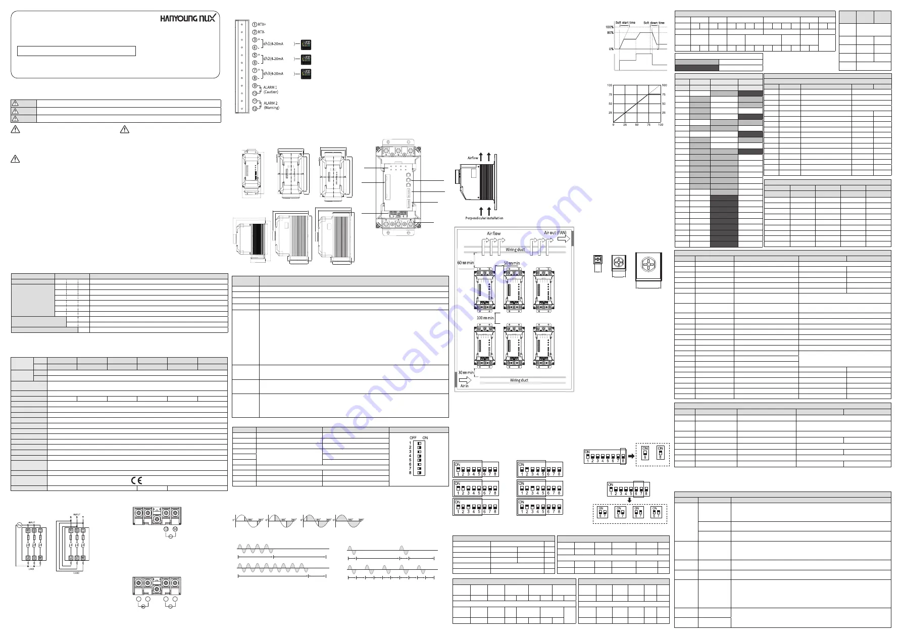
■ Communication protocol selection
• Set the communication protocol with DIP S/W no. 8
RTU
ASCⅡ
■ Address (ID) setting
• Set the ID with DIP S/W no. 1~5
• Set 1 ~ 31 (except 0).
• When communication setting is changed,
the change is applied after reset.
1. Communication method : RS485 2
-
wire half-duplex
2. Communication speed : 2400, 4800, 9600, 19200 bps
3. Maximum number of connections : 31
4. Protocol : ModBus RTU, ModBus ASCII
▍Communication
■ Communication setting (ModBus RTU/ASCⅡ)
Communication settings
Communication speed
2400, 4800, 9600, 19200
bps
Protocol
ModBus RTU
ModBus ASC II
Parity bit
Even
None
bit
Data bit
8
7
bit
Stop bit
1
bit
ID
1 ~ 31
Structure (RTU)
Division Address(ID) Function Start Address No. of Data CRC
Request
1
1
2
2
2
Division Address(ID) Function No. of Data
Data
CRC
Request
1
1
1
2
2
2400 bps
■ Communication speed setting
• Set the communication speed with DIP S/W no. 6 or 7
2400 bps 4800 bps 9600 bps 19200 bps
ID:1
ID:2
ID:3
ID:4
ID:5
ID:6
▍Function descriptions
7. Tighten the screws of the terminal block with the
specified torque.
M3.5: 0.6 ~ 1.2 N.m / M6: 4.41 ~ 4.9 N.m /
M8 : 8.82 ~ 9.80 N.m
▍Specification
▍Suffix code
Model
Code
Content
TPR-2SL
⃞
⃞
- ⃞
Slim type Single phase power regulator
Rated current
040
40 A
055
55 A
070
70 A
090
90 A
130
130 A
160
160 A
Power supply voltage
L
100
-
240 V a.c. (Low)
H
100
-
440 V a.c. (High)
Option
EP
Each phase control (3 device individual control)
※ The circuit power and fan power must be applied separately 100
-
240 V a.c.
※ 130 A, 160 A products are FAN power 24 V d.c. Voltage must be applied.
▍Connection diagram
■ Connection diagram of load terminal
■ Restart function
When a warning or caution alarm occurs, TPR gives alarm 1 or 2 or stop the output.
This function is used to return to normal operation mode when factors caused errors are eliminated.
This function is able to set up when Fuse/Power Supply is in disorder, Heat sink over heat, SCR Short is occurred.
(When Overcurrent is occurred, this function is not working)
0VUQVU
DVSSFOU
*OQVU
TJHOBM
5JNF
5JNF
0
VU
QV
UW
PM
UB
HF
*OQVUTJHOBM
0VUQVUMJNJUWBMVF
1. Please install it perpendicularly. If the product is installed vertically in unavoidable circumstances,
please use 50% of rated current.
2. When multiple products are closely installed, please install them with keeping a distance of more than
a width of 5cm and a length of 10cm as shown in the picture.
3. In order to not block the air flow, please install the wiring duct less than the half of the heat sink height.
4. Please consider whether the air flow is good enough when installing the product. If the ambient
temperature is as low as possible in the inside then the life span of the product is increasing as the
durability and reliability of the product are improving. The operating ambient temperature is 0 ~ 40 ℃.
Please refer to the following graph. However, if the ambient temperature is higher than 40 ℃,
the maximum load current is decreasing like the below.
5. When connecting R and U, please securely fasten them with using crimp connectors since high current
flows into these terminals. If the contact surface of the connectors and terminals are poor, it may lead
to a fire since the wires and terminal gets overheated.
6. Before applying power, this model need more than the third class grounding to prevent electric shock.
This model does not have separate grounding terminal so we suggest using grounding terminal and
bracket together when install this model to a panel.
▍Installation
M3.5
M6
M8
M6
M3.5
M8
M8
M6
M3.5
26.0
15.0
7.3
M3.5
M6
M8
M6
M3.5
M8
M8
M6
M3.5
26.0
15.0
7.3
• Circuit
power
• 40/55/70A
Structure (ASCⅡ)
Division Address
(ID)
Function Start
Address
No. of
Data
LRC
Request
2
2
4
4
2
Division Address
(ID)
Function No. of
Data
Data
LRC
Response
2
2
2
4
2
Example (RTU)
Division Address
(ID)
Function Start Address No. of Data
CRC
Request
0x01
0x03
0x00 0x01 0x00 0x01 0xD5 0xCA
Division Address
(ID)
Function No. of
Data
Data
CRC
Response
0x01
0x03
0x02 0x00 0x00 0xB8 0x44
· Inside of TPR, the fuse is installed in the R,S,T input power supply
portion depending on thespecification of options
· When connecting terminals, please use crimp connectors and
securely fasten them due to the high current flow.
(Max space for solder less terminal connection is
40/55/70 A : 16 mm, 90/130 A : 26 mm)
· Only one channel can be used per temperature controller.
(Serial connection disabled)
· Since the internal GND is not separated, use a module or
temperature controller that has separate analog inputs for each
channel.
■ Connection diagram of input signal and power terminal
*/165
7%$
*/165
7"$
*/165
7"$
*/165
7%$
*/165
7"$
*/165
7"$
● 40/55/70/90 A
● 130/160 A
· Extra input power supply (For circuit power and FAX
operation power) : 100
-
240 V a.c. (13, 14)
Have to connect power to operate unit
(Even if do not need to use FAN).
· Extra input power supply (For circuit power) : 13, 14
· FAN-driven power source : 15, 16
• NO. 1, 2 : RS485 Communication connection port
• NO. 3, 4 : Channel 1 4
-
20 mA d.c. input
• NO. 5, 6 : Channel 2 4
-
20 mA d.c. input
• NO. 7, 8 : Channel 3 4
-
20 mA d.c. input
• NO. 9, 10 : Alarm1 caution
"caution" The alarm is not a serious problem, but it is an alarm that needs to
be checked by the user due to abnormal symptoms. At this time, the TPR
output will go out to normal and only the alarm will be output.
·Caution error : partial load disconnection, heat sink overheat (60 ℃),
overcurrent, power failure, fuse disconnection, FAN error
• NO. 11, 12 : Alarm2 warning
If a "Warning" alarm can cause damage to the product and the load, a
warning will be issued in the following emergency situations. At this
time, the TPR will stop the output itself.
·Warning error : Heat sink overheat (80 ℃), SCR conduction (Short)
※ Once it enters the normal state by supplies of circuit power ( 100 ~ 240
V a.c. ) and load power, the alarm relay is short-circuited and it is
opended when alarm occurs. ("B" contact normally close) In case of
using "A" contact, inquire separately
※ If an alarm condition occurs, an alarm is output after 3 seconds, and
if the alarm condition is released within 3 seconds, an alarm No output.
■ Connection diagram of signal and alarm terminal
*OQVU
*OQVU
*OQVU
▍Installation panel cutout
■ 40/55/70 A
▍Part name and function
[Unit : mm]
■ 90 A
■ 130/160 A
LED indicator
name
Description
POWER
POWER indicator is ON when the power is being supplied to the control unit
CH1
Lights up when an alarm related to channel 1 occurs.
CH2
Lights up when an alarm related to channel 2 occurs.
CH3
Lights up when an alarm related to channel 3 occurs.
L.L
• When the heater is configured in parallel with the partial heater disconnection function, at least one of them is disconnected
This function is to maintain the process while detecting the heater disconnection.
• Detectable when using less than 3 parallel heaters. (In case of 4 or more parallel configurations)
• The total load capacity is not detected within the range of less than 6 A and 0 to 20 %.
• Part heater disconnection detection operation method (scan function)
- Corresponds to phase control, variable cycle control
- After circuit and load power supply is turned on, the LL LED flashes 0 to 100% The heater value is detected while sequentially
outputting the output.
- If the initial scan function is used only once after connecting the heater, the value stored in the internal CPU Therefore, no
further operation is required in the future.
- If you do not use the scan function and leave the initial mode 2 ON, Partial heater disconnection function is activated.
It is not precise in the way that it is detected by calculation formula automatically.
OT
• The LED flashes when the heat sink temperature rises above 60 ° C during control, Operation is normal, and if the
heatsink temperature drops below about 50 °C Will be released.
• If the heat sink temperature rises above 80 ° C during control, the LED will light up and TPR output will stop.
O.C
• When an overcurrent occurs, it will light up if a current above a set value is generated to protect the product and load,
Operation stop (can be set by communication)
• FAN failure: Flashing when FAN fails
EMG
EMG LED lighting situation is as follows.
1. Power failure: The load power is turned on when the circuit powe (100
-
240 V a.c.) is applied Lights when the
heater is disconnected.
2. SCR short: When SCR is shorted, the power is on without control input and TPR output Since the heater continues to
overheat, the current continues to flow without the control input. The EMG LED flashes when it flows. (10 A or more)
■ LED indicator and explanation
Number
OFF
ON
Initial setup MODE
No. 1
-
RESET (Functioning stops)
1. Input mode : 4
-
20 ㎃ d.c.
2. Control Mode: Phase control
No. 2
load volume scan
Partial load disconnection function
No. 3
Restart mode
Not Using
No. 4
-
cycle control fixed cycle method
No. 5
cycle control variable cycle method
No. 4, 5
Phase control
No. 6
Not Using
No. 7
3 channel function fixed
use all 1, 2, 3 channels
No. 8
-
4
-
20 mA d.c.
No. 7, 8
Check 8 LED lights
-
■ Internal dip switch operation
■ Fixed cycle control
As setting the constant cycle of the output, fixed cycle control
is to control the AC power supply repeatedly with a constant
rate of ON/OFF according to the control input.
■ Variable cycle control
Without setting a constant cycle, variable cycle control is to
control AC power supply with using the number of cycle.
■ Phase control
Phase control is to control the AC power supply
applied to the load proportionally according to
the control input signal as changing phase angle
(0 ~ 180 degree) in a each half cycle, 8.33 ms.
0/
0VUQVUDPOUSPM
0''
0/
0''
0/
0''
0/
0''
0/
0''
0/
0''
0VUQVUDPOUSPM
0/
0''
0/
0''
0VUQVUDPOUSPM
0/
0''
0VUQVUDPOUSPM
$POUSPM
0VUQVU
$POUBDU
TJHOBM
$POUSPM
$POUSPM
$POUSPM
0/
0VUQVUDPOUSPM
0''
0/
0''
0/
0''
0/
0''
0/
0''
0/
0''
0VUQVUDPOUSPM
0/
0''
0/
0''
0VUQVUDPOUSPM
0/
0''
0VUQVUDPOUSPM
$POUSPM
0VUQVU
$POUBDU
TJHOBM
$POUSPM
$POUSPM
$POUSPM
0/
0VUQVUDPOUSPM
0''
0/
0''
0/
0''
0/
0''
0/
0''
0/
0''
0VUQVUDPOUSPM
0/
0''
0/
0''
0VUQVUDPOUSPM
0/
0''
0VUQVUDPOUSPM
$POUSPM
0VUQVU
$POUBDU
TJHOBM
$POUSPM
$POUSPM
$POUSPM
Example (ASCⅡ)
Division Address(ID) Function
Start Address
No. of Data
LRC
END
Request 0x01 0x31 0x03 0x33 0x30 0x30 0x30 0x31 0x30 0x30 0x30 0x31 0x46 0x41 0x0D 0x0A
Division Address(ID) Function
No. of
Data
Data
LRC
END
Response 0x30 0x31 0x30 0x33 0x30 0x32 0x30 0x30 0x30 0x30 0x46 0x41 0x0D 0x0A
Protocol MODBUS
RTU
MODBUS
ASCII
Speed
2400, 4800, 9600,
19200 bps
Parity
Even
None
Data bit
8
7
Stop bit
1
1
ID
1 ~ 31
BOLD : RAM DATA
READ
monitoring
READ/WRITE
Configurable
Communication MAP
PROCESS
INFO
CAL
Address
0
100
200
0
System
Scan Start
1
AlarmStatus
Scan Out Mode
2
CH1 Status
CH1 Complete
3
CH2 Status
4
CH3 Status
CH1 LL Rate
5
Rev
CH2 Complete
6
Soft Time
Out Mode
7
CH2 LL Rate
8
CH1 Output
CH3 Complete
9
CH1 Current
10
CH2 Output LL Use Mode
CH3 LL Rate
11
CH2 Current
Protocol
12
CH3 Output
BPS
13
CH3 Current
Parity
14
CH1 Input
Stop Bit
15
CH2 Input
Data Length
16
CH2 Input
Address
17
R.Time
18
CH1 Enable
19
CH2 Enable
20
CH3 Enable
21
CH1 Power Limit
22
CH2 Power Limit
23
CH3 Power Limit
24
CH1 OC Limit
25
CH2 OC Limit
26
CH3 OC Limit
Explanation by address
Process (0 ~ 99)
Address Parameter
Explanation
Setting range
Unit
1
AlarmStatus
Alarm status information
Refer to Bit Information
2
CH1 Status
CH1 Status information
Refer to Bit Information
3
CH2 Status
CH2 Status information
Refer to Bit Information
4
CH3 Status
CH3 Status information
Refer to Bit Information
5
-
-
-
-
6
Soft Time
Soft start Setting time
0 ~ 60
sec
7
-
-
-
-
8
CH1 Output
SCR CH1 Yield
0 ~ 100
%
9
CH1 Current SCR CH1 Load current value 0 ~ CT (max) (x10) A
10
CH1 Output
SCR CH2 Yield
0 ~ 100
%
11
CH1 Current SCR CH2 Load current value 0 ~ CT (max) (x10) A
12
CH1 Output
SCR CH2 Yield
0 ~ 100
%
13
CH1 Current SCR CH2 Load current value 0 ~ CT (max) (x10) A
14
CH1 Input CH1 4 - 20 mA Control signal input
0 ~ 100
%
15
CH2 Input CH2 4 - 20 mA Control signal input
0 ~ 100
%
16
CH3 Input CH3 4 - 20 mA Control signal input
0 ~ 100
%
Calibration (200 ~ 299)
Address
Parameter
Explanation
Setting range
Unit
200
Scan Start
Partial load disconnection scan
0 : Operating, 1:LL Scan
201
Scan Out Mode
Control mode for partial
load disconnection scan
0 : phase control 1 : fixed cycle cycle control
2 : Variable cycle cycle control
202
CH1 Complete
CH1 heater value saved
control, 2 : Variable cycle cycle control
204
CH1 LL Rate
CH1 Parallel heater breaks
1 ~ 6
EA
205
CH2 Complete
CH2 heater value saved
0 : No scan data, 1 : Complete
207
CH2 LL Rate
CH2 Parallel heater breaks
1 ~ 6
EA
208
CH3 Complete
CH3 heater value saved
0 : No scan data, 1 : Complete
210
CH3 LL Rate
CH3 Parallel heater breaks
1 ~ 6
EA
Infomation (100 ~ 199)
Address
Parameter
Explanation
Setting range
Unit
100
System
SCR Product Setup Status
0x0130 : TPR3SLEP
101
-
-
102
-
-
103
-
-
104
105
Rev
SCR Revision
106
Out Mode
Control method setting status
0 : phase control 1 : fixed cycle cycle control
2 : Variable cycle cycle control
110
LL Use Mode
Whether the partial heater
break function is used
0 : Disable partial heater disconnection function
1 : Using partial heater disconnection function
111
Protocol
Protocol setting status
2 : ASCII, 3 : RTU
112
BPS
Communication speed setting status
0 : 2400, 1 : 4800, 2 : 9600, 3 : 19200
113
Parity
Parity bit setting status
0 : None, 1 : Odd, 2 : Even
114
STOP BIT
Stop bit setting state
1, 2
115
DATA LENGTH
Data length
7, 8
116
ADDRESS
ID (SCR communication number)
1 ~ 31
117
R.TIME
Response time
0 ~ 10
118
CH1 Enable
Decide whether to use CH1
0 : Do not use this channel
1 : Use this channel
119
CH2 Enable
Decide whether to use CH2
120
CH3 Enable
Decide whether to use CH3
121
CH1 Power Limit
CH1 output limit setting
0 ~ 100
%
122
CH2 Power Limit
CH2 output limit setting
0 ~ 100
%
123
CH3 Power Limit
CH3 output limit setting
0 ~ 100
%
124
CH1 OC Limit
Set CH1 overcurrent value
0 ~ CT (max)
(x10) A
125
CH2 OC Limit
Set CH2 overcurrent value
0 ~ CT (max)
(x10) A
126
CH3 OC Limit
Set CH3 overcurrent value
0 ~ CT (max)
(x10) A
BIT Information
Parameter
AlarmStatus
CH1 Status
CH2 Status
CH3 Status
Address
1
2
3
4
Bit 0
-
Power Fail
Power Fail
Power Fail
Bit 1
FAN Fail
LL Fail
LL Fail
LL Fail
Bit 2
OC Fail
OC Fail
OC Fail
OC Fail
Bit 3
LL Fail
SCR Short
SCR Short
SCR Short
Bit 4
Over Temp 60
-
-
-
Bit 5
Over Temp 80
-
-
-
Bit 6
SCR Short
-
-
-
Bit 7
Power Fail
-
-
-
Bit 8 ~ 15
-
-
-
-
* 200: If it is 1, the status is being scanned. 0 is displayed after scanning is completed (3 channels are scanned at the same time)
* 201: Control method setting status being scanned
* 202: If it is 1, the scan is completed and the heater value is stored in the internal storage device (If it is 0, it is not saved, not scanned)
* 204: Set to 3 for 3 heaters (Low load malfunction concern Output 20% or less Detection prohibited)
M3.5
M6
M8
M6
M3.5
M8
M8
M6
M3.5
26.0
15.0
7.3
• 90/130/160 A
Explanation about SCR Alarm
Alarm (LED) Alarm Description
Checking list
Power Fail
(EMG
lighting)
When load power is
not applied
1. Confirmation of load power voltage for each channel
(Example: Check 1CH load voltage when 1CH POWER Fail)
2. Check that the load power breaker is ON (Reset, turn on / off)
3. SCR load power input terminal R, S, T wiring check
Fuse disconnected 1. Open the upper case of SCR and check the fuse disconnection
(Shot is normal when measuring the fuse tester after the load power is turned off)
When the heater is
disconnected
1. Check the resistance value of the load connected to the SCR (disconnection and disconnection)
2. Check the SCR heater connection terminals U, V, W wiring
SCR Short
(EMG
flashing)
Internal SCR
element shorted
1. Symptom: When 4 mA and control input are not applied, load current When more than 5 A flows.
2. Confirm: Check several channel SCR Short
3. Generation channel 4
-
20 mA Input part voltage is less than 0.4 V, Ensure current is measured in
clampmeter (SCR failure if confirmed, replacement required)
OC Fail
(OC lighting)
In case of
overcurrent
1. When the current exceeding the OC Limit setting value flows to the load
2. Clamp meter connected to overcurrent identified channels U, V, W Check the current on the wiring.
Fan Fail
(OC flashing)
FAN failure
1. Make sure that the cooling fan on the bottom of the SCR is rotating
2. Make sure that there is foreign substance in the cooling fan
LL Fail
(LL lighting)
One or more
disconnection in
parallel heater
configuration
1. Check if the heater value is saved using the Scan function (communication)
2. If you do not know whether or not you have scanned the control signal (4
-
20 mA)
When there is no scan, DIP SW 2 turns OFF and scan progress, LL LED
When it changes to flashing, it changes to switch ON position again.
3. Check the resistance value of the heater. Comparison of the resistance value of the part
(When the resistance value becomes high)
Over Temp 60
(OT flashing)
Heat sink temperature
Over 60 degrees
1. Check if cooling fan is rotating well
2. Identify the cooling unit inside the panel
3. If an alarm occurs immediately upon power
-
on, the SCR internal fault.
Over Temp 80
(OT lighting)
Heat sink temperature
Over 80 degrees
4FQBSBUFQPXFS
JOQVUUFSNJOBM
4JHOBMBOE
BMBSNUFSNJOBMT
-&%EJTQMBZ
4PGUTUBSUPS
61%08/TFUUJOHWPMVNF
*OUFSOBMEJQTXJUDI
$PNNVOJDBUJPOEJQTXJUDI
-PBEUFSNJOBM
※ The reset operates after turning off the switch 1 and turning it on again through the CPU reset
● SOFT
This is the function to set the soft start and soft up/down times.
(Set via external VR)
- Soft start : It is a function to protect against load with large starting current
(inrush current) and it gradually increases output operates when power is
turned on while control input is applied, and is set to 50 seconds at
maximum VR. (ex : 20 mA : 50 seconds,, 12 mA : 25 seconds,)
- If VR is set to the minimum, this function does not work, and the time is
reduced as VR is changed to the left.
Function to protect power regulator (TPR) and load when overcurrent occurs.
(Phase control only)
- At the time of shipment, it is set to about 120 % of the product rating, and the
overcurrent detection setting value can be changed through communication.
It is a function to limit the output separately from the control input signal. It
can be set through communication and the maximum output amount is
limited according to the set value.
- Set to 100 % at the time of shipment
■ VR Explanation
■ O.C
■ Output limit function


