
4
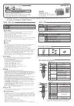
Dimension and connection diagram
87.00
96.90
9.90
1.50
13.75
30.00
6.00
100.00
9.70
ML-D4
PWR
COM
EV
CH1
CH2
ADR
+0
+16
LDR
CH3
CH4
█ Installation by screws
Ø4.20
R2.10
10
9
5.50
ML-D4
PWR
COM
EV
CH1
CH2
ADR
+0
+16
LDR
CH3
CH4
Ø4.20
R2.10
10
9
5.50
ML-D4
PWR
COM
EV
CH1
CH2
ADR
+0
+16
LDR
CH3
CH4
② Push upper hook and
lower hook on the
bottom of the module to
the outside
① Find a place for establishment by referring to the size of the left hole
③ Fix it with M3
screw.
Control
method
ML-D2H
PID (Heating/Cooling simultaneous control) /
2 DOF PID (Single control) / ON-OFF control
ML-D4
2-DOF PID / ON-OFF control
Control operation Selectable between reverse operation (heating) /
direct operation (cooling) (through DR parameter setting)
Proportional band 0 ~ 100 % of FS
Integral time
0 ~ 3,600 Seconds
Derivative time
0 ~ 3,600 Seconds
Cycle time
25 ~ 30 seconds (relay control output), 2 ~ 4 seconds (SSR control output)
ON/OFF control It is possible to set up when proportional band is 0.
Manual reset
It is possible to set up manual reset when integral time is 0 second
Alarm setting range 0 ~ 100% of input range (Absolute alarm), ±100 % of input range (Deviation alarm)
Alarm hysteresis Through EVHY parameter setting
Alarm type
Through EVTY parameter setting (18 types)
Heater
Break
Alarm
ML-D2H
Applicable in ON/OFF control, time proportional control output
(Detection is possible when output ON/OFF time is less than 0.2 seconds.)
Measuring current: 1 – 5 A AC (resolution: 0.5A ± 5 % of FS ± 1 Digit)
CT model name for Heater break alarm: CT-50N
●
Control
Communication protocol RS-232 EIA standard
Max. communication range 15 m
Communication speed 9600 bps
Start bit
1 bit
Data length
8 bits
Parity bit
Even
Stop bit
1 bit
Supported protocol PC-Link
● RS232 communication
Control
output
(ML-D)
RELAY
1a contact
250V AC 3A, 30 V DC 3A
SSR
Limit to approximately 25mA when shorted more than about 12V (load resistance: over 600Ω)
Time resolution: control period 0.1% or the high part among 10ms
SCR
4 - 20 mA DC (Load resistance : lower than 600Ω)
Precision : ±0.1 % of FS (4 - 20 mA range)
● Output
Specification
Display range
±0.3% of Input range, ±1 Digit
Insulation resistance Over 500 V DC 20 MΩ (For Power and input part)
Withstand voltage 750 V AC (For power and input part)
● Quality
Power voltage
24 V DC
Voltage regulation ±10 % of power voltage.
Consumption
voltage
Below 3W
ML-E
Below 5W
ML-D4M, ML-D2HMM
Below 7W
ML-D4S, ML-D4C, ML-D2HSM, ML-D2HSS
Ambient temperature 0 ~ 50 ℃
Ambient humidity 35 ~ 85 % RH (But, not dew condensation )
System requirements Not in a poisonous gas, not in a magnetic filed or in a place where dust is present.
Storage temperature -25 ~ 65 ℃
Weight
Approx. 220g (Excludes the packing box)
● Power supply specification
● RS485 communication
Communication protocol RS-485 EIA standard
Number of maximum
connection
31 units
Communication method 2 wires half duplex
Max. communication range 1200 m
Communication process No process
Communication speed 9600, 19200, 38400, 57600, 76800 bps [Initial value : 9600]
Start bit
1 bit
Data length
7, 8 bits [Initial value : 8]
Parity bit
None, Odd, Even [Initial value : Even]
Stop bit
1 , 2 bits [Initial value : 1]
Response time
Receiving processing time + (response time X 10 ms)
Supported protocol PC-Link , PC-Link with SUM, Modbus ASCII/RTU [Initial value : PC-Link]
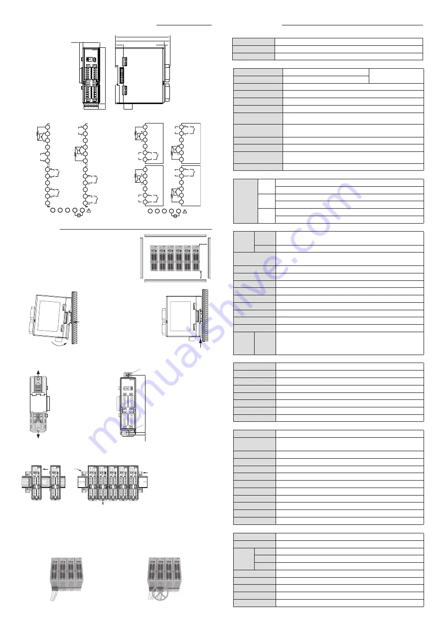
█ Power and communication connection
When making one module by connecting many ML series, apply power line and
communication line to only one unit. When making maximum 32 modules, the maximum
necessary power capacity is 224 W (32units X 7W) (Refer to the Power Specification)
<An example of proper way of use>
<An example of wrong way of use>
█ Installation by DIN Rail
① Hang a hook (A) of
the upper back of the
module to the Din Rail
and install it like (B) by
pressing.
② Push mounting
bracket up and check
if it is hanged properly.
Ⓑ
Ⓐ
1
2
3
4
5
6
A
CH1
B
B
SSR
/SCR
OUT
OUT
OUT
OUT
RLY
CH3
13
14
15
16
17
18
A
B
B
4
5
POWER
24 V d.c
1
TRX+
2
TRX- SG
3
7
8
9
10
11
12
A
CH2
B
B
SSR
/SCR
RLY
SSR
/SCR
RLY
CH4
19
20
21
22
23
24
A
B
B
SSR
/SCR
RLY
● Input
Thermocouple
K, J, E, T, R, B, S, L, N, U, W, PL2
Each channel selected
by INP parameter
RTD
Pt100Ω, KPt100Ω
DC voltage
0 - 100 mV, 1 - 5 V, 0 - 10 V
Sampling period
50 ms.
Input display resolution
Generally below input range's decimal point
Input impedance
Thermocouple and voltage power input : over 1 MΩ
Admissible input
resistance's impact
About 0.2 uV/Ω
Admissible input leading
wire resistance
Thermoresistance
(below 10Ω. but, the resistance of 3 wires should be the same)
Admissible input voltage
within -2 - 5 V (Thermocouple, RTD), within -5 - 12 V (DC voltage)
Input correction
±100% of Input range.
Reference Junction
Complementary Error
±1.5 ℃ (0 ~ 50℃)
Burn-Out Detection
105 % of FS (UP-SCALE)
█ Installation method of Module
For ML series, it is possible to connect maximum 32 units (including ML-E).
When installing module, install them straight in a vertical orientation.
① Accessing the communication
connector by pushing the
module aside.
② Confirm that the bottom hook is
locked properly by pressing.
③ Attach stoppers at both ends
of the module in the rail.
③
1
2
3
4
5
6
A
CH1
CH1
OUT1
CH1
OUT2
CH2
OUT2
CH2
OUT1
B
B
7
8
9
10
11
12
SSR1
/SCR1
CT1
CT2
RLY1
SSR2
/SCR2
RLY2
13
14
15
16
17
18
19
20
21
22
23
24
RLY3
SSR3
/SCR3
RLY4
SSR4
/SCR4
A
B
B
CH2
4
5
POWER
24 V d.c.
1
TRX+
2
TRX- SG
3
█ ML-D2H
█ ML-D4
•Leave over 100mm space in consideration
of ambient temperature and communication parts'
connector when installing and separating module's
main body.
100 mm
100 mm
Installation