
Please read the safety information carefully before the use, and use the product correctly.
The alerts declared in the manual are classified into
‘
DANGER
’, ‘
WARNING
’ and ‘
CAUTION
’ based on its importance
▍Safety information
DANGER
Indicates an imminently hazardous situation which, if not avoided, will result in death or serious injury
WARNING
Indicates a potentially hazardous situation which, if not avoided, could result in death or serious injury
CAUTION
Indicates a potentially hazardous situation which, if not avoided, may result in minor injury or properties damage
Digital temperature controller
BR6
Thank you for purchasing Hanyoung Nux products. Please read the instruction
manual carefully before using this product, and use the product correctly.
Also, please keep this instruction manual where you can view it any time.
MA0601KE220128
INSTRUCTION MANUAL
Name
Sensory type
Range(
℃)
Accuracy
Remark
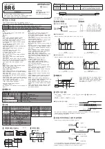
TH540N
Thermistor
-40.0 ~ 90.0
± 1.5 ℃
Max ± 3.5 ℃ temperature deviation may be happen
(± 1.5 ℃ sensor deviation & ± 2 ℃ controller deviation)
※ BR6 applies only to this sensor.
※ Extension of sensor length or modification will cause malfunction.
Ø5.0
40
1,960
Black
White
■ Sensor
(Thermistor/NTC)
▍
Control method for temperature
▍
Connection diagram
: Heating control
: Cooling control
■ Heating/cooling control selection
-20
-25
ON
OFF
OFF
ON
-35
-40
OFF
ON
ON
OFF
50
45
ON
OFF
OFF
ON
70
65
ON
OFF
OFF
ON
-20
-25
ON
OFF
OFF
ON
-35
-40
OFF
ON
ON
OFF
50
45
ON
OFF
OFF
ON
70
65
ON
OFF
OFF
ON
-20
-25
ON
OFF
OFF
ON
-35
-40
OFF
ON
ON
OFF
50
45
ON
OFF
OFF
ON
70
65
ON
OFF
OFF
ON
-20
-25
ON
OFF
OFF
ON
-35
-40
OFF
ON
ON
OFF
50
45
ON
OFF
OFF
ON
70
65
ON
OFF
OFF
ON
Main output
[SV = -25 ℃, dIF = 5, dLy = 0, tyP = CoL]
Main output
[SV = 50 ℃, dIF = 5, dLy = 0, tyP = HEt]
Alarm output (Low limit alarm)
[AtS = -40, AdF = 5, AdL = 0, SAo = 0]
Alarm output (Low limit alarm)
[AtS = 70, AdF = 5, AdL = 0, SAo = 0]
• PV 〉SV → Main output relay "ON" / PV〈 SV → Main output relay "OFF"
• PV 〉SV → Main output relay "OFF" / PV〈 SV → Main output relay "ON"
■ Cooling control(ON/OFF)
■ Heating control(ON/OFF)
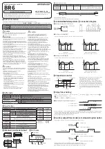
▍
Proportional control
Propotional band
Cycle time
Temperature
Set point
ON
OFF
Set point
Current temperature
Time
• Manipulated variable (output size) of set value operates
by proportioning to deviation and this is known as
proportional control. Also variation range of
manipulated variable from 0 ~ 100 % is known as the
proportional band. Therefore, when proportional band
is less than the current temperature, the manipulated
variable becomes 100 % and when PB is more than the
current temperature, the manipulated variable becomes
0 % and when set value and current temperature
becomes same, the manipulated variable becomes
50 %.
Relay OFF
Relay ON
0S
5S 10S 15S 20S
Relay OFF
Relay ON
• Press key continuously for 3 sec, and then, press key until getting " ". change a set point by
/ key, and preservation it by key.
• [ ] → [ ] → [ ] (0 ~ 240 sec)
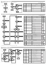
※ In case of Delay Time = 0, Relay is immediately ON when output signal is generating. In case of delay time = 5, Relay is ON after
5 sec. when output signal is generating. In the interval of 5 sec, the output indicator is flickering during delay timer operation.
After the delay time, the output indicator lights as the relay is on.
※ Delay operation is executed only in ON/OFF control.
① Delay time dLy = 0,
② Delay time dLy = 5,
■ Operating description by delay-timer
15 min OFF
15 min OFF
5 min ON
5 min ON
•
When using MOC ‘1’, main output will be OFF automatically as timer is ON.
•
If using MOC function, you can effectively use timer output as a defrosting function.
※ When auxiliary output is timer mode, time unit is selective between “sec” or “min”.
Timer output : ton = 5 min, toff = 15 min
0 : Alarm mode
1 : Timer mode (setting up)
0 : Main output control cancellation
1 : Main output control cancellation
• It is possible to use timer-mode as defrosting function in case of freezer.
28, Gilpa-ro 71beon-gil, Michuhol-gu,
Incheon, Korea TEL : +82-32-876-4697
http://www.hanyoungnux.com
HANYOUNGNUX CO.,LTD
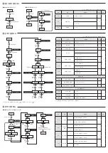
▍
Suffix code
▍
Specification
Model
Code
Description
BR6-
⃞
⃞
⃞
⃞
Digital temperature controller
Control method
F
ON / OFF, Proportional control (selection with parameter)
Input
N
Our dedicated sensor (TH-540N) ※Thermistor (NTC)
Control output
M
Relay output (RELAY output)
S
Voltage pulse output (Voltage pulse output for SSR drive )
Power supply voltage
P3 10 - 24 V d.c.
P4 100 - 240 V a.c. 50/60 Hz
Input sensor
Company exclusive sensor (TH-540N)
※ Thermistor (NTC)
AC power supply
voltage
100 - 240V~
50/60Hz
Input range
-40.0 ~ 90.0 ℃
Display accuracy
± 1 % of FS ± 1 Digit
DC power supply
voltage
10 - 24V , Class2
Main output
Relay output
Contact composition : 1 c, 250 V a.c., 5 A (Resistance load)
SSR
10 - 15 V d.c. (load resistance 500 Ω or more)
voltage
change rate
±10% of supply
voltage
Alarm/Defrost
Relay
Contact composition : 1 c, 250 V a.c., 5 A (Resistive load)
Control operation
Selection of reverse action (heating)/
direct action (cooling) with parameters
AC power
consumption
10.0 VA or less
Setting method
Digital method by setting, increasing and decreasing keys
DC power
consumption
2.0 VA or less
Other function
Deforsting timer, Alarm function
Approval
Ambient
temperature
0 ~ 50
℃
Resistance between
wires
Below 10 Ω for each wire
Ambient humidity
35 ~ 85 % RH (with no condenssation)
Weight
110 g
▍
Dimension and panel cutout
▍Part name
[ Unit : ㎜ ]
Auxiliary output
Setting
Output indicate
Decrease
Increase
Main output
▍Delay Timer Setting
▍
Auxiliary output(Timer-mode) set and operating description
• The contents of this manual may be changed without prior notification.
• Please make sure that the product specifications are the same as you
ordered.
• Please make sure that there are no damages or product
abnormalities occurred during shipment.
• Use this product in the following environments:
- Do not use outdoors.
- use it in the ambient temperature and humidity ranges indicated
in the instruction manual.
- use it in locations where corrosive gases (especially harmful
gases, ammonia, etc.) and flammable gases are not generated.
- use it in places where vibrations and impacts are not directly
applied to product body.
- use it in places without liquids, oils, chemicals, steam, dust, salt,
iron, etc. (pollution degree 1 or 2).
- avoid places where large inductive interference, static electricity,
magnetic noise are generated.
- avoid places with heat accumulation caused by direct sunlight,
radiant heat, etc.
- use it in places with elevation below 2000 m.
- Power input and relay output wires are at least 75 ℃ of heat
resistance and, use copper wires from 18 AWG to 24 AWG.
• The input/output terminals are subject to electric shock risk.
Never let the input/output terminals come in contact with
your body or conductive substances.
• If there is a possibility of a serious accident due to malfunction or
abnormality of this product, install an appropriate protection
circuit on the outside.
• Since this product is not equipped with a power switch and fuse,
install them separately on the outside (fuse rating: 250 Va.c., 0.5 A).
• Please supply the rated power voltage, in order to prevent product
breakdowns or malfunctions.
• The power supply should be insulated and limited voltage/current
or Class 2, SELV power supply device.
• To prevent electric shocks and malfunctions, do not supply power
until the wiring is completed.
• The product does not have an explosion-proof structure, so avoid
using it in places with flammable or explosive gases.
• Never disassemble, modify, process, improve or repair this
product, as it may cause abnormal operations, electric shocks or fires.
• Please disassemble the product after turning OFF the power.
Failure to do so may result in electric shocks, product abnormal
operations or malfunctions.
• Any use of the product other than those specified by the
manufacturer may result in personal injury or property damage.
• Please use this product after installing it to a panel, because there
is a risk of electric shock.
• When used in equipment with a high risk of personal injury or
property damage (examples: medical devices, nuclear control,
ships, aircrafts, vehicles, railways, combustion devices, safety
devices, crime/disaster prevention equipment etc.) install double
safety devices and prevent accidents. Failure to do so may result
in fire, personnel accident or property damage.
DANGER
WARNING
CAUTION
• Please do not wipe the product with organic solvents such as
alcohol, benzene, etc. (wipe it with neutral detergents).
• When water enters, short circuit or fire may occur, so please
inspect the product carefully.
• For thermocouple input, use the predetermined compensating
cable (temperature errors occur when using ordinary cable).
• For RTD input, use a cable with small lead wire resistance and
without resistance difference among 3 wires (temperature errors
occur if the resistance value among 3 wires is different).
• Use the input signal line away from power line and load line to
avoid the influence of inductive noise.
• Input signal line and output signal line should be separated from each
other. If separation is not possible, use shield wires for input signal line.
• Use a non-grounded sensor for thermocouple (using a grounded
sensor may cause malfunctions to the device due to short circuits).
• When there is a lot of noise from the power, we recommend to
use insulation transformer and noise filter. Please install the noise filter
to a grounded panel or structure, etc. and make the wiring of
noise filter output and product power supply terminal as short as
possible.
• Tightly twisting the power cables is effective against noise.
• If the alarm function is not set correctly, it will not be output in
case of abnormal operation, so please check it before operation.
• When replacing the sensor, be sure to turn off the power.
• Use an extra relay when the frequency of operation
(such as proportional operation, etc.) is high, because connecting
the load to the output relay rating without any room shortens the
service life. In this case, SSR drive output type is recommended.
* When using electromagnetic switch: set the proportional cycle
to at least 20 sec.
* When using SSR: set the proportional cycle to at least 1 sec.
• Do not wire anything to unused terminals.
• Please wire correctly, after checking the polarity of the terminals.
• When you install this product to a panel, please use switches or
circuit breakers compliant with IEC60947-1 or IEC60947-3.
• Please install switches or circuit breakers at close distance for
user convenience.
• Please specify on the panel that, since switches or circuit breakers are
installed, if the switches or circuit breakers are activated,
the power will be cut off.
• We recommend regular maintenance for the continuous safe use
of this product.
• Some components of this product may have a lifespan or deteriorate
over time.
• The warranty period of this product, is 1 year, including its
accessories, under normal conditions of use.
• The preparation period of the contact output is required during power
supply. If used as a signal to external interlock circuit, etc. please use a
delay relay together.
• If the user changes the product in case of malfunctions, the
operation may be different due to set parameters differences even
if the model name is the same. So, please check the compatibility.
• Before using the temperature controller, there may be a
temperature deviation between the PV value of the temperature
controller and the actual temperature, so please use the product
after calibrating the temperature deviation.
• The write life of non-volatile memory (EEPROM) is one million
times. When configuring the system, please make sure that
the number of times that data are written to non-volatile memory
does not exceed one million times.
CAUTION