English
_3
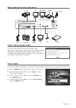
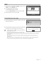
Wiring diagram for external devices
Check Camera Signals Guide
This DVR product automatically recognizes camera signals.
Depending on the installation environment, the automatically recognized
signal may be different from the camera that is actually connected.
If the image is not displayed after the installation, check the signal type of
the connected camera and set it manually.
Video Quality
In order to get better picture quality, it is necessary to choose different EQ value when connecting different distance cable.
1.
Press the [
MENU
] button on the remote control or front panel.
2.
Use the left/right button (◄ ►) to select <
Device
>. Device
setting menu is selected.
3.
Use the up/down buttons (
) to move to <
Camera
>, and
press [
ENTER
] button.
4.
Use the up/down buttons (
) to move to <
Screen Setup
>,
and press [
ENTER
] button.
1
NO
COM
COM COM COM
NC NO
NO
NO
2
3
4
ALARM OUT
G
+ -
TX
+ -
RX
ALARM
RESET
CH1
CH3
CH2
CH4
CONSOLE
HDMI
eSATA
VGA OUT
SERIAL
1
2
3
4
5
6
7
8
9
10
11
12
13
14
15
16
1 2 3 4 5 6 7 8
9 10111213141516
ALARM IN
G
G G
G
NETWORK
USB
AUDIO IN CH5 ~ CH16
VIDEO IN
AUDIO OUT
AUDIO IN
1516
G
AUDIO IN CH5 ~ CH16
14
7
8
4
15
16
SOLE
ONS
CO
HDMI
H
HDMI
HDM
HDMI
DM
DM
DM
DM
DMI
HDMI
HDMI
HDMI
DM
DM
HDMI
HDMI
M
H
VGA OUT
NETWOR
RK
e
eSATA
eSATA
SATA
S
SAT
SAT
T
U
USB
U
U
US
S
S
S
SB
B
B
B
1
2
3
4
ALARM OUT
+
RX
M
G
1
NO
COM
COM COM COM
NC NO
NO
NO
2
3
4
+ -
1
9
EO IN
X
+
R
- +
DE
AUDI
+
TX
IO
+
SERIAL
CH1
CH3
CH2
CH4
AUDIO OUT
DIO O
IN
VI
9
3
4
4
4
4
4
4
4
4
4
5
6
11
12
13
10
2
AUDIO IN
AUDIO IN
VIDEO IN
SPOT
VIDEO OUT (VGA)
NETWORK
AC 100-240V~IN
AUDIO OUT
HDMI
USB
eSATA HDD
Screen Setup
Init
Apply to All CH
CH1
OK
Cancel
48 53 53
3
OK
x
This DVR product automatically recognizes camera signals.
x
Depending on the installation environment,
the automatically recognized signal may be different from the camera that is actually connected.
x
If the image is not displayed after the installation,
check the signal type of the connected camera and set it manually.
Check Camera Signals Guide


