background image

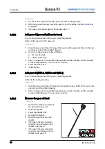
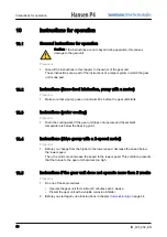
Add gear oil (all gear units)

Only do the procedure if it is necessary to add gear oil.

Caution: Before you use a different type of gear oil that is in the gear unit,

speak to the supplier of the gear oil. Not all gear oils are compatible with each

other. The supplier of the gear oil gives instructions. Obey these instructions.

Procedure

1. Open the gear unit at the oil fill plug. Refer to the sign on the gear unit.
2. Add gear oil.
3. If the gear unit has a motor pump, make sure that the pump goes on for minimum 3

minutes.

4. Measure the level of gear oil.

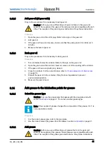
Drain gear oil

Only do the procedure if it is necessary to drain gear oil.

Procedure

1. Put a container below the oil drain. Refer to the sign on the gear unit.
2. Open the gear unit at the oil drain. Gear oil comes out of the opening at the oil drain.
3. If the gear unit has a magnetic plug, clean it.
4. Close the oil drain. For the correct torque, refer to 

Torque values for oil drain screw

on page 58.

5. Discard the gear oil in the container. Obey the local regulations to prevent

environmental pollution.

6. Measure the gear oil level.

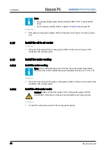
Add grease to the lubrication points for grease

Select the grease type

Caution: Only use the grease type that agrees with the type plate and with

section 

Lubricants

 on page 61. Do not use another grease type.

Note: If the supplier of grease changes the composition of the grease, H.I.T. is

not responsible or liable.

Procedure

1. For the correct grease type, refer to the type plate.
2. Use this data to select the grease from the tables in section 

Lubricants

 on page 61.

Add grease

Caution: Before you use a different type of grease that is in the gear unit,

speak to the supplier of the grease. Not all greases are compatible with each

other. The supplier of the grease gives instructions. Obey these instructions.

8.13.5

8.13.6

8.14

8.14.1

8.14.2

Installation

IM_405_002_EN

41

Содержание P4

Страница 1: ...Installation manual 405 Standardized gear units Hansen Industrial Transmissions nv IM_405...

Страница 2: ...ion or change Details and values given in this document are average values and have been compiled with care They are not binding however and Hansen Industrial Transmissions NV disclaims any liability...

Страница 3: ...in the documentation and on the gear unit 14 4 4 Description of the lubrication of the gear unit 17 4 4 1 Function of lubrication 17 4 4 2 Splash lubrication 18 4 4 3 Force feed lubrication 18 4 5 Bre...

Страница 4: ...32 Attach the gear unit 32 Install the safety cover 32 8 10 Attach the gear unit hollow shafts 32 8 10 1 Install the shrink disk 32 8 10 2 Install the shaft with keyway connection 34 8 10 3 Install th...

Страница 5: ...gear unit solid shafts couplings 48 11 3 Remove the gear unit hollow shafts 48 11 3 1 Disconnect the gear unit from the torque reaction point 48 11 3 2 Remove the shrink disk 48 11 3 3 Disconnect the...

Страница 6: ...ntity type Q4 66 13 15 4 Grease quantity type Q5 66 13 15 5 Grease quantity type Q9 67 13 16 Grease quantity for lubrication points at labyrinth seals LSS 68 13 16 1 Grease quantity type 68 13 16 2 Gr...

Страница 7: ...kW Motor Torque kNm Service Factor on Motor Power Absorbed Power kW Absorbed Torque kNm Service Factor on Absorbed Power Direction of Rotation low speed shaft Mass of the gear unit1 kg ATEX Specifica...

Страница 8: ...ion C Maximum peak temperature of the gear oil in the oil bath dur ing operation C Grease type Storage and protection The gearbox is adequately treated for storage and corrosion protection up to2 1 ye...

Страница 9: ...e of the Manual The user and or purchaser bears all risks Should further information be desired or should particular problems arise which are not covered sufficiently for the users and or purchaser s...

Страница 10: ...nd titles in this document The steps in procedures have numbers 123 if the sequence is important The lists and steps with bullets are used if the sequence is not important The lists with letters abc a...

Страница 11: ...pproved installation engi neers Installation manual IM_ Approved installation engi neers Maintenance manual MM_ Approved maintenance en gineers Logbook Approved installation engi neers Approved mainte...

Страница 12: ...e document and the related documents in a dry and clean location Make sure that the document and the related documents are available to all personnel Abbreviations Abbreviation Description H I T Hanse...

Страница 13: ...er gearbox driven equipment couplings mounting conditions and sources of excitation rests with the owner of the installation H I T is not responsible for system dynamics and related damage Type plate...

Страница 14: ...ease quantity type P Number of lubrication points Q Grease type Z Remarks Note The certified drawing shows more data illustration of the gear unit type connection diagrams dimensions Signs in the docu...

Страница 15: ...plug Breather plug Anti humidity Condensation drain Lubrication point for grease Lubrication point for grease at bearing Lubrication point for grease at labyrinth seal Direction of rotation clockwise...

Страница 16: ...dicator Gauge glass Overflow Inspection opening P Pump lubrication Filter Filter with mechanical contamination indicator Filter with electrical contamination indicator C Temperature indicator Temperat...

Страница 17: ...r vibration sensor Ground connection ATEX Description of the lubrication of the gear unit Function of lubrication Lubrication is necessary for these functions To prevent metal to metal contact in gear...

Страница 18: ...es of oil pumps Integrated pump one of the shafts of the gear unit operates the oil pump Motor pump a motor operates the oil pump The lubrication can be circulation lubrication or pressure lubrication...

Страница 19: ...hafts As a standard the shafts of the gear unit can turn in two directions If the shafts of the gear unit can only turn in one direction a sign on the gear unit and the certified drawing shows this 4...

Страница 20: ...gineers obey all related safety regulations and are approved to safely install the gear unit It is the responsibility of the company that owns the system where the gear unit is part of to make sure th...

Страница 21: ...unit is a part of and the attached parts cause vibrations and noise To agree with local legislation it can be necessary to decrease the noise of the drive group and the attached parts Speak to H I T...

Страница 22: ...th the gear unit insofar as the gear unit operates within the service and rating conditions put forward in the order acknowledgment and on the certified drawing Non compliance with these instructions...

Страница 23: ...damage to gears and bearings Use an anti brinelling device On site transport Lift the gear unit Note The certified drawing shows more data dimensions mass H I T makes sure that all necessary lifting p...

Страница 24: ...assis only use the lifting points on the gear unit Caution If parts of the gear unit are removed to move the gear unit make sure that water or contamination cannot come into the lubrication system or...

Страница 25: ...cables A is 45 in the plane of the long side of the gear unit 2 For all other gear units make sure that all lifting cables B are vertical and parallel to each other 3 Connect the lifting equipment to...

Страница 26: ...ffect on the gear unit Extended storage outdoors for maximum 2 years extended outdoor storage The storage period starts when the gear unit leaves H I T For this date refer to the dispatch form Procedu...

Страница 27: ...el ground f Put a plastic cover on the gear unit to prevent contamination with dust 3 Each year do these inspections on the gear unit a Examine the paint on the gear unit for damage b Examine all bare...

Страница 28: ...rees with the shipping papers 6 If the gear unit shows damage or does not agree with your order tell H I T immediately Installation instructions for parts that are not part of the gear unit Procedure...

Страница 29: ...hafts during the installation of the coupling hubs is lower than 100 C Procedure 1 Install the spacer between the shaft shoulder and the coupling hub 2 Install the coupling hubs on the shaft extension...

Страница 30: ...ake sure that only the external loads that agree with the order acknowledgement or the certified drawing work on the gear unit This includes the loads of the machine in operation Install gear units wi...

Страница 31: ...fication Refer to section Position of the gear unit on page 53 Align the LSS multi stage Caution Obey the specifications If not the lifetime of the bearings and the couplings will be decreased Procedu...

Страница 32: ...t specifications gear units with solid shafts on page 54 2 Tighten the bolts For the correct torque refer to section Bolt specifications gear units with solid shafts on page 54 3 Do a check on the pos...

Страница 33: ...tween the parts A D and E If there is an opening water can come in and cause corrosion Note The parts F G and H are not a part of the gear unit Speak to H I T if it is necessary that H I T supplies th...

Страница 34: ...in several steps clockwise and increase the torque gradually to the correct torque Make sure to keep inner ring and outer ring parallel during the whole tightening process 4 Remove the threaded rod th...

Страница 35: ...installation key on the machine shaft Procedure 1 Install the O ring A on the machine shaft B 2 Install the installation key C in the keyseat D of the machine shaft 3 Make sure that the short leg of t...

Страница 36: ...ompare the clearance with the specification Refer to the certified drawing 3 If the clearance is not correct use a new final key Install the final key Caution Make sure that there is no opening betwee...

Страница 37: ...ll the torque arm Procedure 1 Attach the gear unit to a torque reaction point Use a torque arm Refer to the certified drawing for the location of the torque arm on the gear unit Prestress the disk spr...

Страница 38: ...e gear unit as a part of a circuit to ground other machines Caution Install a ground connection If not electric current can cause damage to the gears and the bearings Procedure 1 Ground the gear unit...

Страница 39: ...y This condition causes damage to the gear unit Procedure 1 Refer to the service manual of the lubrication and cooling system Instructions for force feed lubrication pressure lubrication Procedure 1 R...

Страница 40: ...d drawing You can use an oil pump 4 Lower the motor base 5 Install the belt Add gear oil QHR 4 QVR 3 and QVR 4 Only do the procedure the first time you install the gear unit Add oil to the bearing hou...

Страница 41: ...magnetic plug clean it 4 Close the oil drain For the correct torque refer to Torque values for oil drain screw on page 58 5 Discard the gear oil in the container Obey the local regulations to prevent...

Страница 42: ...ooling Install the water cooling Note If the certified drawing does not show the cooling water temperature the water flow on the certified drawing is applicable to water at 20 C 70 F Procedure 1 Obey...

Страница 43: ...ations on page 70 3 While you connect the cooling coil A hold the connection B with an open spanner C to prevent torsion on the cooling coil Installation instructions heater Procedure 1 Make sure that...

Страница 44: ...top Caution Do not turn the gear unit in the incorrect direction This condition causes damage to the backstop Procedure 1 Make sure that the backstop operates correctly Start instructions heater Proce...

Страница 45: ...OIL GUARDTM system on the HSS If you see leaks at this location speak to H I T Procedure 1 Do a check on the gear oil level Refer to section Measure the gear oil level on page 40 2 While the gear unit...

Страница 46: ...if the gear unit does not operate and the ambient temperature is below the freezing point Instructions drive group with a 2 speed motor Procedure 1 Before you change from the higher to the lower speed...

Страница 47: ...the gear unit Protect the gear unit with a volatile corrosion inhibitor Procedure 1 Add a volatile corrosion inhibitor to the gear oil Speak to the supplier of the gear oil for instructions Do not ad...

Страница 48: ...ad or torque on the gear unit Remove the gear unit solid shafts couplings Procedure 1 Disconnect the coupling If H I T supplied the coupling refer to the certified drawing If H I T did not supply the...

Страница 49: ...y from each other 5 Remove the shrink disk 6 If the shrink disk is dirty Clean the shrink disk Apply a solid lubricant to the machined surfaces Refer to section Lubrication on page 58 Remove the gear...

Страница 50: ...ocedure 1 Install these parts Installation disk A Bolts B for the type of bolts refer to the certified drawing Bolt to remove the gear unit C 2 To remove the gear unit from the machine shaft tighten t...

Страница 51: ...ve environmental regulations when disposing used oil Do not dump it on garden soil wooded areas into open streams or down sewage drains Make sure to remove any spillage at once Sort metal components c...

Страница 52: ...rque seal Loctite 7417 torque Marque or similar Paint specification Parameter Specification Primer Two component polyamide cured epoxy pre fabrication primer 20 m Finish Two component high build polya...

Страница 53: ...Specification dr r d Misalignment equation where dr measured radial misalignment mm r maximum permitted radial misalignment mm d measured angular misalignment mm maximum permitted angular misalign men...

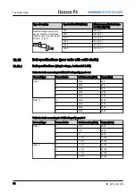
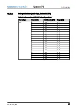
Страница 54: ...ge horizontal LSS Table for bolts according to DIN 267 bolt quality grade 8 8 Gear unit type Gear unit size Bolt dimension ISO Torque Nm QHP 1 C M20 335 D M24 675 E M24 675 F M30 1350 G M30 1350 QHP 1...

Страница 55: ...e 8 8 Gear unit type Gear unit size Bolt dimension ISO Torque Nm QH A M16 180 B M20 335 C M24 675 D M24 675 E M30 1350 F M30 1350 G M36 2350 H M36 2350 J M36 2350 K M36 2350 L M42 3800 M M42 3800 N M4...

Страница 56: ...dimension UNC Torque lbf in QH A 5 8 1550 B 3 4 2950 C 7 8 4850 D 1 6000 E 1 1 4 12000 F 1 1 4 12000 G 1 1 2 21000 H 1 1 2 21000 J 1 1 2 21000 K 1 1 2 21000 L 1 3 4 33650 M 1 3 4 33650 N 2 50750 P 2 5...

Страница 57: ...Gear unit size Bolt dimension ISO Torque Nm QV A M16 180 B M20 335 C M24 675 D M30 1350 E M30 1350 F M36 2350 G 2 stage M36 2350 G 3 stage and 4 stage M42 3800 H M42 3800 J M42 3800 K M42 3800 L M48 5...

Страница 58: ...3 4 33650 H 1 3 4 33650 J 1 3 4 33650 K 1 3 4 33650 L 2 50750 M 2 50750 N 2 50750 P 2 50750 Q 2 50750 R 2 1 4 81050 S 2 1 4 81050 T 2 1 4 81050 Torque values for oil drain screw Dimension of the drain...

Страница 59: ...1 SDA2D240001 570 H 901 SDA2D260001 570 J 901 SDA2D280001 570 K 901 SDA2D320001 990 L 901 SDA2D340001 990 M 901 SDA2D360001 990 N 901 SDA2D390001 1480 P 901 SDA2D420001 1480 Q 901 SDA2D440001 1480 R 9...

Страница 60: ...Y mm inch QH A2 0 7 0 028 QH B2 0 7 0 0 28 QH C2 0 9 0 035 QH D2 0 9 0 035 QH E2 1 0 0 039 QH F2 1 0 0 039 QH G2 1 0 0 039 QH H2 1 0 0 039 QH C3 0 7 0 028 QH D3 0 9 0 035 QH D4 0 9 0 035 QH E3 0 9 0 0...

Страница 61: ...mperature range for corrosion inhibi tor C F 4 15 70 60 158 General specifications for gear oil per viscosity grade Viscosity grade AGMA SUS 100 F ISO VG150 4 690 ISO VG220 5 1100 ISO VG320 6 1600 ISO...

Страница 62: ...00 XP 220 Mobilgear 600 XP 320 Mobilgear 600 XP 460 REPSOL Super Tauro FND 220 Super Tauro FND 320 SHELL Omala F 150 Omala F 220 Omala F 320 Omala F 460 SHELL Omala S2 GX 150 Omala S2 GX 220 Omala S2...

Страница 63: ...MOBIL Mobilgear SHC XMP 150 Mobilgear SHC XMP 220 Mobilgear SHC XMP 320 Mobilgear SHC XMP 460 Mobil SHC Gear Series 150 Mobil SHC Gear Series 220 Mobil SHC Gear Series 320 Mobil SHC Gear Series 460 M...

Страница 64: ...320 Carter SH 460 Table 4 Related grease Note For all synthetic gear oils you can only use the grease type in the table below Supplier Related grease NLGI grade 2 Related grease NLGI grade 3 FAG Arca...

Страница 65: ...0 50 100 D 60 80 60 130 100 120 E 90 110 90 180 130 170 F 120 150 120 240 180 220 G 170 200 170 220 320 H 180 230 180 280 400 J 220 280 220 320 410 K 260 320 260 320 500 L 320 400 320 410 590 M 340 41...

Страница 66: ...Lubrication point Gear unit size Lubrication point A g B g Z 10 20 A 20 20 B 30 30 Grease quantity type Q5 A B A Lubrication point B Lubrication point Gear unit size Lubrication point A g B g Z 10 20...

Страница 67: ...e B Lubrication point at the upper side C Lubrication point at the upper side D Lubrication point at the upper side E Lubrication point at the upper side Gear unit size Lubrication point A g B g C g D...

Страница 68: ...ease quantity single stage Gear unit type Grease quantity g QHRC1Z N 75 QHRD1Z N 75 QHRF1Z N 45 QHPC1 10 QHPD1 10 QHPE1 15 QHPF1 25 QHPG1 35 QVPZ1 10 QVPB1 10 Grease quantity multi stage Gear unit typ...

Страница 69: ...5 P Solid 230 Q Solid 240 R Solid 255 Grease quantity for lubrication points at labyrinth seals HSS Grease quantity type The grease quantities only apply to the lubrication points that are indicated o...

Страница 70: ...Grease quantity g Z 10 A to H 10 J to T 20 Cooling water specifications Parameter Specification MPa bar psi Maximum water pres sure on the cooling coils 0 8 8 116 Quality Fresh water or salt water 13...

Страница 71: ...Technical data IM_405_002_EN 71...

Страница 72: ...ium Phone 32 3 45012 11 Fax 32 3 45012 20 info hansenindustrialgearboxes com Sumitomo SHI Cyclo Drive Germany GmbH CycloStra e 92 85229 Markt Indersdorf Germany Phone 49 8136 66 0 Fax 49 8136 5771 mar...

Отзывы: