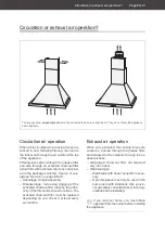
Assembly
Page EN-18
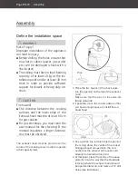
(10)
(8)
(9)
(2)
2. Screw the other four mounting rails (2)
with four screws (8), four washers (10) and
four nuts (9) to the previously attached
mounting rails in such a way that the ex-
haust hood sits at the desired height later
on.
Please note! The upper mounting rails
must protrude by at least one hole width
over the mounting rails, so that they can
be attached to the base plate (6) later on.
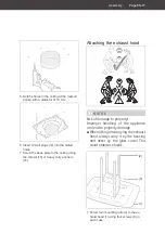
(5)
(11)
(13)
3. Only for exhaust air operation:
Carefully insert both plastic check valves
(13) into the air outlet opening at the top of
the appliance (gently bend the flaps a little
so as not to break off the sensitive plastic
tabs).
Attach the exhaust air hose (5) opening
with a diameter of 153 mm (see marking
on the hose) to the vent opening and se-
cure it with cable ties (11).
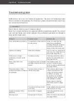
(2)
(4)
4. Remove the protective foil from the upper
part of the flue screen (3) and carefully
insert it into the lower section of the flue
screen (4).
Please note! The parts are not square. If
the upper section does not fit, turn it by a
quarter turn.
5. Place the assembled flue screen (3)+(4)
over the mounting rails (2) above the ex-
haust hood. The end with the ventilation
slots in the upper section (3) must be
facing upwards. The flue screen must fit
exactly into the recess of the glass hood
(quarter turn as required)
6. Remove any remaining blue protective film
from the flue screen.
Содержание 79017465
Страница 26: ...Technische Daten Seite DE 26 ...
Страница 52: ...Technical Specifications ...


