background image

5

2020/09

1 About These Instructions

These operating instructions describe the structure, functions and the use of the product and will 

help you to operate the product as intended. Read these instructions carefully before using the 

product. This is to avoid possible damage to persons, property or the device. Retain the instructions 

for future use during the service life of the product. If the product is passed on, pass on these instruc

-

tions as well.

1.1

Target groups

These instructions are aimed a qualified personal and must be carefully read by anyone mounting, 

commissioning, operating, maintaining, dismantling or disposing of the device.

1.2

Documentation concept

This manual contains all information about the CANopen-Gateway of the product line BL20-ECO 

(BL20-E-GW-CO).
The following chapter contain a short BL20-description, a description of the used field bus system, 

exact information about function and structure of the field bus specific CANopen-gateway as well 

as all bus specific information concerning the connection to automation devices, the maximum sys

-

tem extension etc. 
The bus-independent I/O-modules of the BL20-system as well as all bus independent information 

as mounting, labeling etc. are described in a separate manual. 

BL20 I/O-modules (Turck-documentation no.: German D300716; English D300717)

In addition to that, the mentioned manual contains a short description of the I/O-ASSISTANT, the 

project planning and configuration software tool for Turck I/O-systems.

Содержание BL20-ECO

Страница 1: ...Your Global Automation Partner BL20 E GW CO ECO Gateway for CANopen Instructions for Use...

Страница 2: ...2 Hans Turck GmbH Co KG T 49 208 4952 0 F 49 208 4952 264 more turck com www turck com...

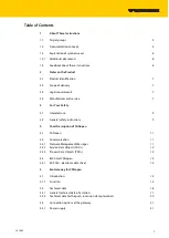
Страница 3: ...ety 3 1 Intended use 9 3 2 General safety instructions 9 4 Short Description of CANopen 4 1 CANopen 11 4 2 Communication 11 4 2 1 Network Management Messages 11 4 2 2 Service Data Objects SDOs 12 4 2...

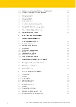
Страница 4: ...31 7 1 1 Complete planning 31 7 1 2 Maximum system extension 32 7 2 Power supply 34 7 2 1 Power supply to the gateway 34 7 2 2 Module bus refreshing 34 7 2 3 Creating potential groups 34 7 2 4 C rail...

Страница 5: ...Protection against high frequency interference signals 43 8 3 6 Mounting rails 43 8 3 7 EMC compliant cabinet installation 44 8 4 Shielding of cables 45 8 4 1 Potential compensation 46 8 4 2 Switchin...

Страница 6: ...Hans Turck GmbH Co KG T 49 208 4952 0 F 49 208 4952 264 more turck com www turck com 4...

Страница 7: ...e 1 2 Documentation concept This manual contains all information about the CANopen Gateway of the product line BL20 ECO BL20 E GW CO The following chapter contain a short BL20 description a descriptio...

Страница 8: ...re as informative and as clear as possible If you have any suggestions for improving the design or if some information is missing in the docu ment please send your suggestions to techdoc turck com DAN...

Страница 9: ...Germany Turck supports you with your projects from initial analysis to the commissioning of your applica tion The Turck product database contains software tools for programming configuration or com mi...

Страница 10: ...Notes on the Product Hans Turck GmbH Co KG T 49 208 4952 0 F 49 208 4952 264 more turck com www turck com 8...

Страница 11: ...a CANopen network and forwards the data collected from the field by the BL20 I O modules within the BL20 sta tion to the higher level CANopen master The devices may only be used as described in these...

Страница 12: ...For Your Safety Hans Turck GmbH Co KG T 49 208 4952 0 F 49 208 4952 264 more turck com www turck com 10...

Страница 13: ...connectors and bit rates on the basis of ISO 11898 4 2 Communication The lower layers of CANopen are defined according to the ISO OSI model in the ISO 11898 standard Communication between the individu...

Страница 14: ...the Boot up message to indicate to the NMT master that it has reached the state pre operational This occurs whenever the device initially boots up but also after a power out during operation The Boot...

Страница 15: ...r The time period between Sync messages is defined by the Communication Cycle Period which may be reset by a configuration tool to the application devices during the boot up process There can be a tim...

Страница 16: ...aluation Event driven PDOs Synchronous PDOs clock synchronous Remote requested PDO polling 4 3 1 EDS file electronic data sheet CANopen nodes are embedded in the CANopen structure by the help of a sta...

Страница 17: ...hnical data a description of addressing and status displays 5 1 1 Function The BL20 gateways enable BL20 modules to operate on CANopen The gateway is the connection between the BL20 modules and a CANo...

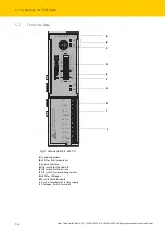
Страница 18: ...or the bit rate F DIP switch for terminating resistor G LEDs for CANopen H Push In for field supply I Push In terminals for system supply J CANopen Push In terminals Fig 1 Gateway BL20 E GW CO Unlock...

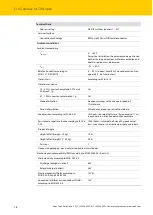
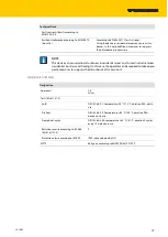
Страница 19: ...max system extension Approx 0 5 A Permissible range According to EN 61 131 2 18 30 V DC Max field current IL 8 A Residual ripple According to EN 61 131 2 Isolation voltage UL to USYS 500 Veff Voltage...

Страница 20: ...vibration Frequency sweeps with a change in speed of 1 Octave min Period of oscillation 20 frequency sweeps per axis of coordinate Shock resistant according to IEC 68 2 27 18 shocks sinusoidal half w...

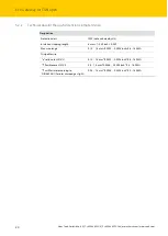
Страница 21: ...tial business and trading In this case the operator can be required to take appro priate measures to suppress the disturbance at his own cost Designation Approvals CE cULus Tests EN 61131 2 Cold DIN I...

Страница 22: ...class IP20 not evaluated by UL Insulation stripping length 8 mm 1 0 32 inch 0 039 Max wire range 0 14 1 5 mm2 0 0002 0 0023 inch2 26 16 AWG Crimpable wire e solid core H 07V U 0 14 1 5 mm2 0 0002 0 00...

Страница 23: ...has push in tension clamps for Field supply voltage UL GNDL and System supply USYS GNDSYS Fig 3 Push in tension clamp terminals at the gateway NOTE The minimum temperature rating of the cable to be c...

Страница 24: ...ssignment has to be used Standard commercial cables will have to be rewired I O ASSISTANT KABEL BL20 BL67 5 3 3 Connection through an I O ASSISTANT cable The I O ASSISTANT cables have a PS 2 male conn...

Страница 25: ...23 2020 09 Pin BL20 gateway PS 2 female connector SUB D interface at the PC Pin 1 CLK DTR DSR 4 6 2 GND GND 5 3 DATA 4 n c DATA2 RxD 2 5 5 V RTS 7 6 n c CLK2 TxD 3...

Страница 26: ...open bus can use Node IDs up to 127 Each Node ID can only be assigned once in the entire CANopen bus structure The gateway s field bus address results from the addition of the valences 20 to 25 of the...

Страница 27: ...valid bitrate has been detected it will not be changed The autobaud phase is signaled by alternating fast flashing 10 Hz of the ERR LED red of the BUS LED green Fig 8 DIP switches for setting the bit...

Страница 28: ...the system supply Usys and the field supply UL 3 Set the Node ID to 0 The device stores the station s configuration This is indicated by the flashing of the IOs LED After the storage procedure the IOs...

Страница 29: ...upplied Check the wiring at the gateway or at the Bus refreshing module Green 5 V DC operating voltage is present firmware is active gateway is ready for operation and transfer Green flashing 1 Hz Und...

Страница 30: ...nodes Red Faulty or interrupted communi cation between BL20 CANopen gateway and other CANopen nodes CAN BusOff Heartbeat error Guarding error Transmit timeout Check that the fieldbus ends with a termi...

Страница 31: ...29 2020 09 6 BL20 Communication in CANopen NOTE The CANopen description for BL20 can be found in a separate manual BL CANopen object register D301230 under www turck de...

Страница 32: ...BL20 Communication in CANopen Hans Turck GmbH Co KG T 49 208 4952 0 F 49 208 4952 264 more turck com www turck com 30...

Страница 33: ...onis provided by acommon externalvoltagesource independent of the number of bus refreshing modules used in the station This prevents the occurrence of poten tial equalization currents within the BL20...

Страница 34: ...Feeding modules BL20 PF 24VDC D BL20 PF 120 230VACD They are used to build up potential groups or in case of insufficient power supply Ensure that a sufficient number of Bus Refreshing and Power Feed...

Страница 35: ...BL20 E 16DO 24VDC 0 5A P 2 25 mA BL20 16DO 24VDC 0 5A P 3 120 mA BL20 32DO 24VDC 0 5A P 5 30 mA BL20 1AO I 0 4 20MA 4 39 mA BL20 2AO I 0 4 20MA 7 40 mA BL20 2AO U 10 0 10VDC 7 43 mA BL20 2DO R NC 1 2...

Страница 36: ...the base module If the power supply from the module bus is not guaranteed the software I O ASSISTANT 3 FDT DTM generates an error message if the user activates the DTM Additional functions Verify sta...

Страница 37: ...ple BL20 S4T SBCS The corresponding connection level is indicated on these modules by a thick black line The black line is continuous on all I O modules On power distribution modules the black line i...

Страница 38: ...into a ground reference system please read chapter 8 Guidelines for Electrical Installation NOTICE Missing potential isolation Destruction of module electronic Ensure that after using the C rail for t...

Страница 39: ...rface and the rotary coding switches must remain in place due to EMC and ESD requirements Abb 5 Using the C rail as protective earth and for the power supply with relay modules 23 22 21 13 12 11 23 23...

Страница 40: ...d Firmware can be downloaded via the service interface on the gateway using the software tool I OASSISTANT More information is available in the program s online help NOTICE Pulling or plugging of modu...

Страница 41: ...patible cable routing the cables should be grouped as follows Various types of cables within the groups can be routed together in bundles or in cable ducts Group 1 shielded bus and data cables shielde...

Страница 42: ...nt where the cables enter the building 8 1 4 Transmission cable The slaves on the bus are connected to one another with fieldbus lines that correspond to the Devi ceNet specification ODVA Spec Rel V2...

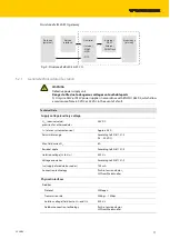
Страница 43: ...nstallation The block diagram shows the arrangement of a typical BL20 with the ECO gateway BL20 E GW CO 8 2 2 Potential free installation In a potential free installation the reference potentials of c...

Страница 44: ...s All inactive metal components for example switchgear cabinets switchgear cabinet doors sup porting bars mounting plates top hat rails etc must be connected to oneanother over a largesur face area an...

Страница 45: ...ails All mounting rails must be mounted onto the mounting plate with a low impedance over a large surface area and must be correctly earthed Use corrosion resistant mounting rails Mountthe mounting ra...

Страница 46: ...ontact with the cabinet hous ing C Protective conductor rail The protective conductor rail must also be connected over a large surface area to the mounting plates and addi tionally with an external ca...

Страница 47: ...area The shield rail must have a low impedance for example fixing points of 10 to 20 cm apart and be connected to a reference potential area The cable shield should not be severed but routed further w...

Страница 48: ...tion cables that are routed on both sides the compen sationlineimpedancemustbeconsiderably smaller thanthatoftheshield connection max 10 of shield connection impedance Should the length of the compens...

Страница 49: ...Switching inductive loads In the case of inductive loads a protective circuit on the load is recommended 8 4 3 Protection against Electrostatic Discharge ESD Abb 5 Potential compensation Between swit...

Страница 50: ...Guidelines for Electrical Installation Hans Turck GmbH Co KG T 49 208 4952 0 F 49 208 4952 264 more turck com www turck com 48...

Страница 51: ...49 2020 09 9 BL20 Approvals for Zone 2 Division 2 NOTE The Zone 2 approval certificates for BL20 can be found in a separate manual for approv als D301255 under www turck de...

Страница 52: ...BL20 Approvals for Zone 2 Division 2 Hans Turck GmbH Co KG T 49 208 4952 0 F 49 208 4952 264 more turck com www turck com 50...

Страница 53: ...Over 30 subsidiaries and over 60 representations worldwide www turck com D301108 2020 09 D301108...

Отзывы: