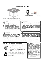
Hanover ORL4PCCFPSW2-BRY Скачать руководство пользователя страница 4

Page 4

ASSEMBLY INSTRUCTIONS
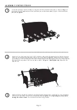
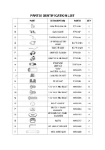
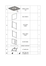
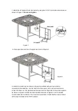
1

2

3

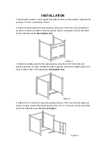
Assemble furniture on a smooth, non-abrasive surface.

by using two

5/16"x40 mm bolts and washers as shown in

. Guide the bolts through holes in back frame, into

pre-drilled holes in the

.

and back frame

by using four 5/16"x25 mm bolts and washers as shown in

.

A

and seat frame by using two 5/16"x25 mm bolts and two 5/16"x40 mm bolts and four washers as

shown in

.

Fig.1

Hand tighten only.

Fig.2 Hand tighten only.

Fig.3 Hand tighten only.

Attach the back frame to right arm

right arm

Attach the seat frame to right arm

ttach the left arm

to back

B

D

I

G

H

Fig.1

I

G

H

A

Fig.2

I

F

H

I

F

H

C

Fig.3

I

F

H

I

G

H

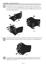
Attach the complete base to the complete seat by using four 5/16"x40 mm bolts and washers as shown
in

. Guide the bolts through holes in base, into the pre-drilled holes in the seat.

Fig.4

Hand tighten only.

Using the hex bolt driver provided, tighten all bolts.

Test the operation of glider. Gliding

motion should be smooth. Adjust tension on the glider brackets, nuts and bolts as needed. Cover nuts
and bolts with covers provided.

Do not over tighten bolts. If nuts and bolts are

too tight or too loose, the glider will not function properly.
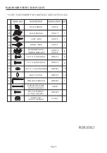
I

G

H

Fig.4

E

I

G

H

Содержание ORL4PCCFPSW2-BRY

Страница 1: ...mer Service Hotline at 1 800 416 3511 Between 9 00 AM and 5 00 PM Eastern Time Monday through Friday Or visit our website at www hanover products com To expedite any future warranty claims please reta...

Страница 2: ...arm shown in Attach back of love seat arm by inserting two mm bolts with washers through holes in the back portion of love seat frame and into the holes in the rear portion of the love seat arm as sho...

Страница 3: ...5 X 1 5 MM WASHER LEFT ARM RIGHT ARM BOLT COVER HEX BOLT DRIVER FOOT CAP 1 FACTORY ASSEMBLY HW0005 HW0022 HW0006 FC0030 1 12 HW0275 12 4 5 16 X 25 MM BOLT HW0186 1 1 1 1 BACK FRAME SEAT FRAME PARTS L...

Страница 4: ...t arm right arm Attach the seat frame to right arm ttach the left arm to back B D I G H Fig 1 I G H A Fig 2 I F H I F H C Fig 3 I F H I G H Attach the complete base to the complete seat by using four...

Страница 5: ...G H I J DESCRIPTION ORDER PART QTY GLIDER BRACKET FACTORY ASSEMBLY ST4 8 X 25 BOLT FACTORY ASSEMBLY FOOT CAP FACTORY ASSEMBLY FC0013 6 5 16 X 25 MM BOLT HW0186 8 5 16 X 40 MM BOLT HW0275 HW0005 8 5 X...

Страница 6: ...n adjustment alteration service or maintenance can cause injury or property damage Read the installation operating and maintenance instructions thoroughly before installing or servicing this equipment...

Страница 7: ...FICE ELBOW FP0310 1 G IGNITION MODULE FP0006 1 H PROPANE ORIFICE ZCF0021 1 I AAA BATTERY 1 5V HW0705 1 J LAVA ROCK SET FP0002 1 K FOOTCAP FC0559 4 L 1 4 X 15 MM BOLT HW0034 8 M 1 4 X 20 MM BOLT HW0036...

Страница 8: ...U FIREPIT TABLE TOP 1 V BACK PANEL 1 W LEFT SIDE PANEL 1 X RIGHT SIDE PANEL 1 Y DOOR PANEL 1 Z MIDDLE SUPPORT 1 AA LP SUPPORT 1 BB BOTTOM TOP CONNECTOR 1...

Страница 9: ...oles in the side panels Hand tighten only Figure 2 3 Attach the middle support to the side panels by using four 1 4 x15 mm bolts and washers as shown in Figure 3 Guide the bolts through the holes in t...

Страница 10: ...top connector to the right side panel as shown in Figure 5 Do not over tighten Figure 5 6 With the help of another person carefully place the table top onto the table base After making any necessary a...

Страница 11: ...ure 9 pre fitted with gas hose which is connected to the table top into the hole of the door panel then use hex bolt driver to screw 1 4 x5mm nut the gas tank has fixed as shown in Figure 9a Connect t...

Страница 12: ...n all bolts Note each bolt must be tightened a few revolutions at a time Repeat until all bolts are tight Do not over tighten Over tightening may strip bolts Cover all bolts with covers 12 Pour the la...

Страница 13: ...s found close the tank valve and tighten all connections NOTE NEVER USE A FLAME TO CHECK FOR LEAKS BATTERIES Make sure the control knob is in the OFF position Unscrew the push button cap on the igniti...

Страница 14: ...should pop back out and then remain lit Note If the fire does not light turn the knob to the OFF position and wait five 5 minutes before trying again 3 To turn down the flame push the control knob in...

Страница 15: ...le Check that the electrode is not cracked or broken Burner won t light Lack of oxygen Remove excess lava rocks or fire ices from around the ignition well Thermocouple not in flame Check that the tip...

Отзывы: