13
Hangar 9 Toledo Special Assembly Manual
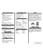
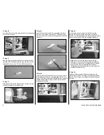
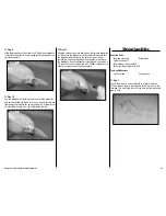
Step 4
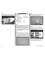
Use a drill and 5/32-inch (4mm) drill bit to drill a hole
through the firewall at the mark made in the previous step.
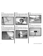
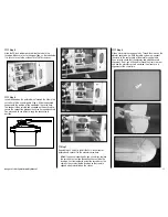
Step 5
Use medium grit sandpaper to scuff the outside of the
12-inch (305mm) pushrod tube. This will provide a better
surface for the CA to adhere to when gluing the tube in
position.
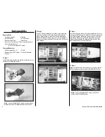
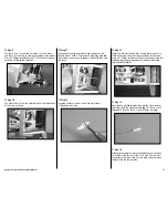
Step 6
Insert the throttle tube into the hole drilled in Step 4. Leave
roughly 1
1
/
2
-inch (38mm) exposed. Use medium CA to glue
the tube to the firewall.
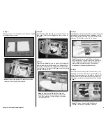
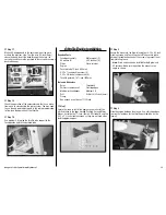
Step 7
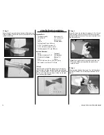
Position the engine on the mounts so the face of the drive
washer is 4
1
/
2
-inches (114mm) forward of the firewall. Use
a pencil or drill bit to transfer the locations for the engine
mounting bolts onto the engine mounts. Use a clamp to hold
the position of the engine while marking the engine mounts.
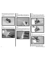
Step 8
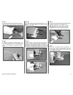
Use a drill and 5/32-inch (4mm) drill bit to drill the holes for
the engine mounting screws in the engine mounts.
hint
: If you have access to a drill press, it is highly
recommended that you use it. Using a drill press for
drilling these holes will guarantee they are straight.
Step 9
Use four 8-32 x 1-inch machine screws, four #8 washers
and four 8-32 lock nuts to secure your engine to the mounts.
Use a #2 Phillips screwdriver and 11/32-inch box wrench or
nut driver to tighten the hardware.


