


HAMWORTHY HEATING LTD Page 500001065/B
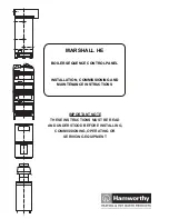
MARSHALL HE
5
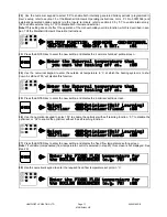
4.3 Control Inputs Connections
4.3.1
Safety Interlock Circuit
This circuit operates at safety extra low voltage
and MUST only be connected to volt free switching
devices.
Connect all of the required safety devices in
series (see Figure 5/Page 21) between terminals ‘+’
and 7 of the ‘inputs’ terminal rail.
Note!
If no safety devices are to be connected these
two terminals must be linked to allow correct
operation of the controller.
A minimum cable size of 0.75 mm
2
is
recommended for this circuit. Refer to the IEE
Regulations for the correct cable specification.
4.3.2
External Timeclock (Optional)
This circuit operates at safety extra low voltage
and MUST only be connected to a volt free switching
timeclock.
Connect the timeclock to terminals ‘+’ and 1 of
the ‘inputs’ terminal rail (see Figure 5/Page 21). A
minimum cable size of 0.75 mm
2
is recommended for
this circuit.
Refer to the IEE Regulations for the correct cable
specification.
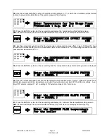
4.3.3 Remote Override Switch (Optional)
The remote override feature is not available when
an external timeclock is connected to the Marshall HE
system.
This switch is connected across terminals ‘+’ and
1 of the ‘inputs’ terminal rail (see Figure 5/Page 21).
A minimum cable size of 0.75mm² is recommended
for this circuit.
Refer to the IEE Regulations for the correct cable
specification.
Note!
This circuit operates at safety extra low
voltage, mains voltages MUST NOT be fed onto
these terminals.
4.3.4 Remote Holiday Override Switch (Optional)
This switch is connected across terminals ‘+’ and
8 of the ‘inputs’ terminal rail (see Figure 5/Page 21).
A minimum cable size of 0.75mm2 is recommended
for this circuit.
Refer to the IEE Regulations for the correct cable
specification.
Note!
This circuit operates at safety extra low
voltage, mains voltages MUST NOT be fed onto
these terminals.
4.4 Temperature Sensors
4.4.1
General
The temperature sensors are wired using 2 core,
screened cable (Beldon 8451 specification), HHL Part
No. 533901259).
PVC cable sleeving should be used to insulate
the shield conductor to prevent the possibility of it
contacting the other conductors or any of the sensor
or controller pcb components.
The flow and external sensor housings
incorporate a cable inlet threaded to accept a 20 mm
cable gland or conduit connector. When fitted with
such a connector the external sensor is IP65 rated.
It is strongly recommended that the sensor
cables are routed separately from mains power
cables.
4.4.2 Water Flow Temperature Sensor
The standard flow sensor is an insertion type
consisting of a brass probe mounted to a plastic
housing. The sensor is supplied with a brass pocket
with a ½" BSP parallel thread (see Figure 7/Page 23).
The sensor must be installed at the outlet of the
flow header from the boiler system. There must be
no connections taken from the flow header between
the boilers and the sensor position.
Fit the sensor pocket to a ½" BSP socket welded
to the flow header, allowing an insertion depth to the
centre line of the pipe (see Figure 7/Page 23).
Alternatively, the sensor can be installed at a pipe
bend as shown in Figure 7/Page 23.
Insert the sensor probe into the pocket and fix in
place with the locking screw on the side of the
pocket.
An optional ‘strap on’ type sensor is available as
an alternative to the standard sensor. If this sensor is
utilised it must be firmly fixed to the flow header pipe
with the strap and hooks supplied (See Figure 8/Page
24), to ensure a good contact between the surface of
the pipe and the sensor.
When fitted, wire the sensor as shown in Figure
5/Page 21 and replace the sensor housing cover.
4.4.3
External Temperature Sensor
The optional external sensor should be mounted
on an outside, north facing wall, away from any air
vents, pipes, illuminated signs or any other device
that could affect the ambient temperature of the
outside air.
The sensor can be fixed to the wall utilising the
mounting holes in its plastic housing, or held in place
by the cable conduit (see Figure 9/Page 25).
Note!
Ensure that a suitable cable gland or conduit
connector is utilised to provide the required sealing of
the sensor housing.
When fitted, wire the sensor as shown in Figure
5/Page 21 and replace the sensor housing cover.
4.4.4
Room Temperature Sensor
Содержание MARSHALL HE
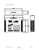
Страница 21: ...HAMWORTHY HEATING LTD Page 500001065 B MARSHALL HE 17 Figure 2 Overall Dimensions...
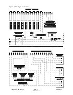
Страница 22: ...HAMWORTHY HEATING LTD Page 500001065 B MARSHALL HE 18 Figure 4 Marshall HE System Schematic...
Страница 23: ...HAMWORTHY HEATING LTD Page 500001065 B MARSHALL HE 19 Figure 5 Site Wiring Connection Details...
Страница 24: ...HAMWORTHY HEATING LTD Page 500001065 B MARSHALL HE 20 Figure 6 Example Boiler Connection Schemes...
Страница 33: ...HAMWORTHY HEATING LTD Page 500001065 B MARSHALL HE 29 NOTES...
Страница 34: ...HAMWORTHY HEATING LTD Page 500001065 B MARSHALL HE 30 NOTES...
Страница 35: ...Notes...


