HAMPTON BAY LILLYCREST II Скачать руководство пользователя страница 11

10

Mounting the fan-motor assembly (standard mount)
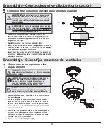
5


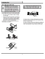
Align the locking slots of the canopy (C) with the two screws 
(GG) in the mounting bracket (A). Push up to engage the slots 
and turn clockwise to lock in place.


Firmly tighten the two mounting screws (GG).


Install the two canopy screws (HH) (saved from Assembly 
Step 1 “Preparing for mounting”) into the holes in the canopy 
(C) and tighten firmly.


Install the decorative canopy ring (II) by aligning the ring’s 
slots with the screws in the canopy (C). Rotate the ring clock-
wise to lock in place.

WARNING:

 When using the standard ball/downrod mounting, the 

tab in the ring at the bottom of the mounting bracket must rest in 
the groove of the hanger ball. Failure to properly seat the tab in 
the groove could cause damage to the wiring.

WARNING:

 The locking slots of ceiling canopy are provided only 

as an aid to mounting. Do not leave the fan assembly unattended 
until all four canopy screws are engaged and firmly tightened.

Assembly - Hanging the Fan (continued)

E

A

II

C

HH

Assembly - Attaching the Fan Blades

Fastening the blade brackets to 
the motor

1


Remove the rubber plug (FF) from the access hole (ZZ) on the 
switch cup. 


Fasten the blade brackets (H) to the fan-motor assembly (E) by 
inserting the alignment post into the slot on the bottom of the 
motor and tightening the pre-installed blade bracket screws  
by inserting a screwdriver through the access hole (ZZ).


Repeat this step for the remaining blade bracket by rotating 
the motor until the next blade bracket screw can be accessed 
through the access hole (ZZ) in the switch cup cover.


Replace the rubber plug (FF).

WARNING:

 Remove the rubber motor stops on the bottom of 

the fan before installing the blades or testing the motor.

NOTE:

 Your fan features revolutionary advancements for quick 

and easy blade installation, including an alignment post and 
captive blade bracket screws.

IMPORTANT:

 The switch cup cover has an access hole (ZZ) 

to allow the screwdriver to reach the screws in the blade 
bracket. Position the blade bracket on the motor and tighten 
by inserting the screwdriver through the access hole (ZZ).

E

H

ZZ

Содержание LILLYCREST II

Страница 1: ...ctrical tape Phillips screwdriver F A B D C E G H I Installation continued Read and save these instructions 1 The power supply to the remote control receiver should be connected through a mains switch...

Страница 2: ...the purchase of this ceiling fan We strive to continually create quality products designed to enhance your home Visit us online to see our full line of products available for your home improvement ne...

Страница 3: ...ust be UL General Use Switches Refer to the instructions packaged with the light kits and switches for proper assembly 9 After making electrical connections spliced conductors should be turned upward...

Страница 4: ...r the warranty invalid There is no other express warranty Hampton Bay hereby disclaims any and all warranties including but not limited to those of merchantability and fitness for a particular purpose...

Страница 5: ...Extra blade bracket screw 1 BB Plastic wire connector 3 CC Hanger pin 1 DD Locking pin 1 EE Pull chain 1 FF Water proof plug 1 Pre Installation continued HARDWARE INCLUDED NOTE Hardware not shown to...

Страница 6: ...bly 1 C Canopy 1 D Coupling cover 1 E Fan motor assembly 1 Part Description Quantity F Switch cup 1 G Blade 5 H Blade bracket 5 IMPORTANT This product and or components are governed by one or more of...

Страница 7: ...he appropriate fasteners and materials The outlet box and its bracing must be able to fully support the weight of the moving fan at least 35 lbs Do not use a plastic outlet box The illustrations below...

Страница 8: ...p of the fan motor assembly E Remove the canopy ring II from the canopy C by turning the ring counterclockwise until it unlocks Remove the mounting bracket A from the canopy C by loosening the two can...

Страница 9: ...he outlet box as shown Securely tighten the two mounting screws KK 1 WARNING To reduce the risk of fire electric shock or personal injury mount to an outlet box marked Acceptable for fan support of 35...

Страница 10: ...ly If using the 4 5 in ball downrod assembly B provided you can cut the lead wires to your desired length no shorter than 12 in This will make extra room in the canopy C if you do not wish to cut the...

Страница 11: ...tightened Assembly Hanging the Fan continued E A II C HH Assembly Attaching the Fan Blades Fastening the blade brackets to the motor 1 Remove the rubber plug FF from the access hole ZZ on the switch c...

Страница 12: ...g the Fan Blades Assembly Attaching the Switch Cup Attaching the switch cup 1 Remove the four screws VV from the switch cup cover below the fan motor assembly E Connect the wires from fan motor assemb...

Страница 13: ...of the blades forward switch left or reverse switch right A Warm weather Forward A downward airflow creates a cooling effect This allows you to set your air conditioner on a higher setting without aff...

Страница 14: ...the ceiling above the tip of one of the blades Measure from a point on the center of each blade to the point on the ceiling Measure this distance Rotate the fan until the next blade is positioned for...

Страница 15: ...problems missing parts Before returning to the store call Hampton Bay Customer Service 8 a m 7 p m EST Monday Friday 9 a m 6 p m EST Saturday 1 855 HD HAMPTON HAMPTONBAY COM Retain this manual for fu...

Страница 16: ...iladores de techo en una fuente de corriente de CA de 110 120 V y 60 Hz 5 No instalar en lugares h medos ni sumergir en agua S lo para uso en interiores 6 No hales ni recortes los cables terminales 7...

Страница 17: ...ste ventilador de techo Nos esforzamos en crear continuamente productos de calidad dise ados para mejorar tu hogar Vis tanos por Internet para ver nuestra l nea completa de productos disponibles a fin...

Страница 18: ...mblar bien consulta las instrucciones adjuntas a los kits de luces e interruptores 9 Despu s de concluir las conexiones el ctricas debes voltear los conductores empalmados hacia arriba y meterlos con...

Страница 19: ...presa Por este medio y en el alcance permitido por la ley Hampton Bay queda exonerado de toda garant a incluso pero sin limitarse a ellas aquellas de comercializaci n e idoneidad para un fin determina...

Страница 20: ...de aspas 1 BB Conector de pl stico para cables 3 CC Pasador de soporte 1 DD Pasador de cierre 1 EE Interruptor de cadena 1 FF Tap n impermeable 1 Preinstalaci n continuaci n HERRAJES INCLUIDOS NOTA L...

Страница 21: ...Cubierta del acoplamiento 1 E Conjunto motor ventilador 1 Pieza Descripci n Cantidad F Caja del interruptor 1 G Aspa 5 H Soporte de aspa 5 IMPORTANTE Este producto y o sus componentes est n protegidos...

Страница 22: ...les apropiados La caja el ctrica y su soporte deben sostener completa mente el peso en movimiento del ventilador al menos 35 libras No uses una caja el ctrica de pl stico Las ilustraciones a continuac...

Страница 23: ...n la parte superior del conjunto motor ventilador E Retira de la cubierta C su aro II gir ndolo hacia la izquierda hasta liberarlo Retira el soporte de montaje A de la cubierta C aflojando los dos tor...

Страница 24: ...usta firmemente los dos tornillos de montaje KK 1 ADVERTENCIA Para reducir el riesgo de incendio descarga el ctrica u otras lesiones instala s lo en una caja el ctrica clasificada como Apropiada para...

Страница 25: ...bajante esfera Si usas el conjunto de tubo bajante esfera B de 4 5 plg 11 4 cm incluido puedes recortar los cables terminales al largo deseado no menos de 12 plg 30 5 cm Esto dejar m s espacio en la c...

Страница 26: ...aje C mo colgar el ventilador continuaci n E A II C HH Ensamblaje C mo fijar las aspas del ventilador C mo montar los soportes de las aspas al motor 1 Retira el tap n de goma FF del orificio de acceso...

Страница 27: ...caja del interruptor 1 Quita los tres tornillos VV de la cubierta de la caja del interruptor debajo del conjunto del motor del ventilador E Conecta los cables del conjunto del motor del ventilador E...

Страница 28: ...el sentido de giro de las aspas hacia delante hacia la izquierda o en reversa hacia la derecha A Clima c lido Hacia adelante Un flujo de aire descendente surte un efecto refrescante Esto permite fijar...

Страница 29: ...debe a que las aspas no est n al mismo nivel Verifica este nivel seleccionando un punto en el techo sobre la punta de una de las aspas Mide desde un punto en el centro de cada aspa al punto en el tec...

Страница 30: ...lo a la tienda llama al servicio al cliente de Hampton Bay De 8 00 a m a 7 00 p m Hora Est ndar del Este entre lunes y viernes y los s bados de 9 00 a m a 6 00 p m Hora Est ndar del Este 1 855 HD HAMP...

Отзывы: