background image

8

Assembly - Close-To-Ceiling Mount

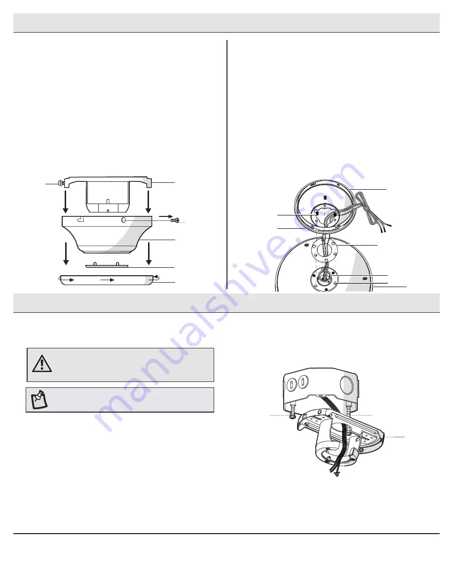
Assembly - Hanging the Fan


Remove three of the six screws and lock washers (KK) (every 
other one) securing the motor collar (M) to the top of the fan-
motor assembly (D).


Route the wires exiting the top of the fan-motor assembly (D) 
through the rubber gasket (DD) aligning the holes in the rubber 
gasket (DD) with the three screws holes in the fan-motor 
assembly (D), then through the canopy (C) (make sure the slot 
openings are on top).


Place the canopy (C) over the collar at the top of the fan-motor 
assembly (D), aligning the mounting holes with the holes in 
the motor and fasten using the three screws and lock-washers 
(KK) removed previously. Tighten the mounting screws 
securely.

C

DD

D

KK

K

M

KK

Attaching the fan to the electrical 
box


Pass the 120-Volt supply wires through the center hole in the 
slide-on mounting bracket (A).


Install the slide-on mounting bracket (A) on the outlet box by 
sliding the slide-on mounting bracket (A) over the two screws (LL) 
provided with the outlet box. If necessary, use leveling washers 
(not included) between the slide-on mounting bracket (A) and 
the outlet box. The flat side of the slide-on mounting bracket (A) 
should face toward the outlet box, as shown.


Securely tighten the two mounting screws (LL).

1

WARNING:

 To reduce the risk of fire, electric shock 

or personal injury, mount to an outlet box marked 

“Acceptable for fan support of 35 lbs. (15.9 kg) or less,” 

and use the screws provided with the outlet box.

LL

LL

A

Routing the wires

Preparing for mounting

2

1


Remove the canopy ring (K) from the canopy (C) by turning the 
ring counterclockwise until it unlocks.


Remove the mounting bracket (A) from the canopy (C) by 
loosening the two canopy screws (HH) located in the “L 
shaped” slots.


Remove and save the two canopy screws (GG) in the round 
holes. This will enable you to remove the mounting bracket 
(A).


Remove the decorative canopy bottom cover (L) from the 
canopy (C) by pressing the three studs.

L

C

A

K

GG

HH

NOTE:

 The mounting bracket (A) is designed to slide into 

place on an outlet box with the outlet box screws (LL).

Содержание 1002 707 953

Страница 1: ...ugh the purchase of this ceiling fan We strive to continually create quality products designed to enhance your home Visit us online to see our full line of products available for your home improvement...

Страница 2: ...d be turned upward and pushed carefully up into the outlet box The wires should be spread apart with the grounded conductor and the equipment grounding conductor on one side of the outlet box 10 All s...

Страница 3: ...er the warranty invalid There is no other express warranty Hampton Bay hereby disclaims any and all warranties including but not limited to those of merchantability and fitness for a particular purpos...

Страница 4: ...re connector 3 BB Hanger pin 1 CC Locking pin 1 Part Description Quantity DD Rubber gasket 1 EE Extra blade bracket screw 1 FF Pull chain 2 Pre Installation continued HARDWARE INCLUDED NOTE Hardware n...

Страница 5: ...t kit fitter assembly 1 Part Description Quantity F Motor collar cover 1 G Blade bracket with pre installed screws 5 H Blade 5 I Shatter resistant shade 3 J LED bulb 9W 3 IMPORTANT This product and or...

Страница 6: ...he appropriate fasteners and materials The outlet box and its bracing must be able to fully support the weight of the moving fan at least 35 lbs Do not use a plastic outlet box The illustrations below...

Страница 7: ...ar on top of the fan motor assembly D Remove the canopy ring K from the canopy C by turning the ring counterclockwise until it unlocks Remove the mounting bracket A from the canopy C by loosening the...

Страница 8: ...e on mounting bracket A over the two screws LL provided with the outlet box If necessary use leveling washers not included between the slide on mounting bracket A and the outlet box The flat side of t...

Страница 9: ...with this fan is designed to accept up to one 12 gauge house wire and two wires from the fan If you have larger than 12 gauge house wiring or more than one house wire to connect to the fan wiring con...

Страница 10: ...ing screws Install the two mounting screws saved from Assembly Step 1 Prepairing for mounting into the holes in the canopy C and tighten firmly Install the decorative canopy ring K by aligning the rin...

Страница 11: ...ockwise to lock in place Immediately tighten the two mounting screws firmly Install the two mounting screws saved from Assembly Step 1 Prepairing for mounting into the holes in the canopy C and tighte...

Страница 12: ...screws RR on the switch cup cover of the light kit fitter assembly E Connect the wires from the light kit fitter assembly E to the wires from the switch cup of the fan motor assembly D by connecting t...

Страница 13: ...ter resistant shades to cool completely before removing FF D I J Turn on the power and check the operation of the fan The fan pull chain controls the fan speed as follows 1 pull High 2 pulls Medium 3...

Страница 14: ...f the blades Measure from a point on the center of each blade to the point on the ceiling Measure this distance Rotate the fan until the next blade is positioned for measurement Repeat for each blade...

Страница 15: ...ns problems missing parts Before returning to the store call Hampton Bay Customer Service 8 a m 7 p m EST Monday Friday 9 a m 6 p m Saturday 1 855 HD HAMPTON HAMPTONBAY COM Retain this manual for futu...

Страница 16: ...Hampton Bay al comprar este ventilador de techo Nos esforzamos continuamente en crear productos de calidad dise ados para mejorar tu hogar Vis tanos por Internet para ver nuestra l nea completa de pr...

Страница 17: ...a y meterlos con cuidado en la caja el ctrica Los cables deben estar separados con el cable a tierra y el conductor a tierra del equipo a un lado de la caja el ctrica 10 Todos los tornillos de fijaci...

Страница 18: ...zado invalidar la garant a No hay ninguna otra garant a expresa Por este medio Hampton Bay queda exonerado de todas y cada una de las garant as incluyendo pero sin limitarse a aquellas de comercializa...

Страница 19: ...r de soporte 1 CC Pasador de cierre 1 Pieza Descripci n Cantidad DD Junta de goma 1 EE Tornillo adicional para soporte de aspas 1 FF Interruptor de cadena 2 Preinstalaci n continuaci n HERRAJES INCLUI...

Страница 20: ...kit de luces 1 Pieza Descripci n Cantidad F Cubierta del collar n del motor 1 G Soporte de aspa con tornillos preinstalados 5 H Aspa 5 I Pantalla resistente a impacto 3 J Bombilla LED 9W 3 IMPORTANTE...

Страница 21: ...riales apropiados La caja el ctrica y su soporte tienen que sostener completamente el peso en movimiento del ventilador al menos 35 libras No uses una caja el ctrica de pl stico Las ilustraciones a co...

Страница 22: ...del motor del ventilador D Retira el aro K de la cubierta C gir ndolo en sentido con trario a las manecillas del reloj hasta que se libere Retira el soporte de montaje A de la cubierta C aflojando lo...

Страница 23: ...zante A sobre la caja el ctrica desliz ndolo A sobre los dos tornillos LL suministrados con la caja el ctrica Si es necesario usa arandelas niveladoras no incluidas entre el soporte de montaje desliza...

Страница 24: ...el ctrico dom stico de calibre 12 y dos cables del ventilador Si tienes un cableado dom stico superior a calibre 12 o m s de un cable dom stico para conectar al cableado del ventilador consulta a un e...

Страница 25: ...tornillos de montaje guardados en el paso 1 del ensamblaje c mo preparar la instalaci n en los orificios de la cubierta C y apri talos firmemente Instala el aro de cubierta decorativo K alineando sus...

Страница 26: ...los dos tornillos de montaje Instala los dos tornillos de montaje guardados en el paso 1 del ensamblaje c mo preparar la instalaci n en los orificios de la cubierta C y apri talos firmemente Instala...

Страница 27: ...el kit de luces E Conecta los cables del conjunto del soporte del kit de luces E a los cables de la caja del interruptor del conjunto del motor del ventilador D usando los enchufes con adaptadores mol...

Страница 28: ...enfr en por completo antes de retirarlas FF D I J Enciende la fuente de electricidad y verifica el funcionamiento del ventilador La cadena del interruptor controla las velocidades del ventilador de l...

Страница 29: ...smo nivel Veri fica este nivel seleccionando un punto en el cielo raso sobre la punta de una de las aspas Mide desde un punto en el centro de cada aspa al punto en el cielo raso Mide esta distancia Gi...

Страница 30: ...er a la tienda llama al Servicio al Cliente de Hampton Bay de lunes a viernes entre 8 00 a m y 7 00 p m Hora Est ndar del Este y los s bados de 9 00 a m a 6 00 p m Hora Est ndar del Este 1 855 HD HAMP...

Отзывы: