background image

28

!

"

!

Bandsaw

N2-38 / N3800 / N4400

Operation

Warning! Risk of injury due to insufficient preparation!

It is only permitted to switch on the machine if, for the work at hand, the required preconditions are 

fulfilled and any preliminary work is completed. Therefore, the adjusting, fitting and operating instructions 

(see the corresponding chapters) must be read before switching on the machine.

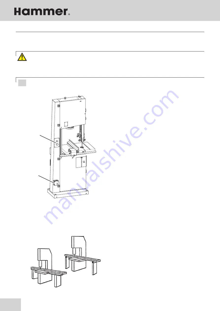
Fig. 7-7: On- and Off switch

7.6 Switching on the machine / Switching off the machine

All uses which differ from the following work techniques 

have not been intended for this machine and are therefore 

not authorised.

Feed the workpiece with constant speed and pressure for-

wards without applying sideways pressure Do not interrupt 

the cut and do not pull the workpiece backwards When 

cutting large pieces, use appropriate table extensions or 

roll supports.

Fig. 7-8: Rip cut

7.7.1 Longitudinal cut along the marked line

7.7 Authorised working techniques

Attention! The machine will not start with the doors open and will automatically stop if doors are opened 

during operation. (Only valid for the CE-version !)

The bandsaw has an On- and Off switch.
Green push button: 

Switch machine on

Red push button: 

Switch off the machine.

Optional equipment: Additional emergency stop

!

 On/Off switch

"

 Additional emergency stop

Содержание N2-38

Страница 1: ... Manual Bandsaw N2 38 N3800 N4400 Dok ID 500033 901_02 Englisch 2023 05 31 GER Original operating manual language Other languages Translation of the original operating manual Download your local language http fg am ba manuals DE EN FR PL SV RO IT DA NL ES ET CZ LV SL FI PT HU RU ...

Страница 2: ... vicinity of the machine so that it is accessi ble to operators when using maintaining or repairing the machine Attention The machine must be inspected immediately upon arrival If the machine has been damaged during transport or if any parts are missing a written record of the problems must be submitted to the forwarding agent and a damage report compiled Also be sure to notify your supplier immed...

Страница 3: ...3 Bandsaw N2 38 N3800 N4400 ...

Страница 4: ...0 2 9 Other risks 11 2 10 Foreseeable misuse 11 3 Declaration of Conformity 12 4 Specifications 14 4 1 Dimensions and weight 14 4 2 Noise emission 14 4 3 Operation and storage conditions 15 4 4 Electrical connection Drive motor 15 4 5 Dust Extractors 16 5 Assembly 17 5 1 Overview 17 5 2 Data plate 18 5 3 Automatic braking system 18 5 4 Brake system USA model 18 6 Setup and installation 19 6 1 Safe...

Страница 5: ...workpieces in the transverse direction 29 7 7 3 Cutting workpieces on the upright edge 29 7 7 4 Longitudinal cut of narrow or thin workpieces with the longitudinal guide fence 29 7 7 5 Mitre cuts 30 7 7 6 Circular cuts 30 7 7 7 Diagonal cross cut of rectangular workpieces 30 8 Service 31 8 1 Safety instructions 31 8 2 Tightening replacing the drive belt 31 8 3 Replacing the rubber wearing surface ...

Страница 6: ...ention regulations and general safety regulations Before beginning any work on the machine ensure that the manual in particular the chapter entitled Safety and the respective safety guidelines has been read in its entirety and fully understood This manual is an integral part of the machine and must therefore be kept in the direct vicinity of the machine and be accessible at all times If the machin...

Страница 7: ...ails may be found on our website www felder group com 1 6 Spare parts If unauthorised spare parts are fitted into the machine all warranty service compensation and liability claims against the manufacturer and their contractors dealers and representatives shall be rejected Use only genuine spare parts supplied by the manufac turer 1 7 Disposal If the machine is to be disposed of separate the compo...

Страница 8: ...s other than those it was designed for The chapter entitled Safety offers an overview of all the important safety considerations necessary to optimise safety and ensure the safe and trouble free operation of the machine To further minimise risks the other chapters of this manual contain specific safety instructions all marked with symbols Besides the various instructions there are a number of pict...

Страница 9: ...t all functions and potential dangers of the machine Spe cialist staff is a term that refers to those who due to their professional training know how experience and knowledge of relevant regulations are in a position to assess delegated tasks and recognise potential risks If the personnel lack the necessary knowledge for wor king on or with the machine they must first be trained Responsibility for...

Страница 10: ...hine are based on the results of this analysis and correspond to state of the art technology The machine is considered operationally safe when used properly Nevertheless there are some remaining risks that must be considered The machine runs at high electrical voltage Before carrying out any maintenance cleaning and repair work switch off the machine and ensure that it can not be accidentally swit...

Страница 11: ...ols and accessories that are not permitted by the manufacturer Use only genuine spare parts supplied by the manufacturer Making changes and modifications to the machine Bridging or adaptation of protective equipment During operation Processing of workpieces that are too large or too heavy Processing of very small workpieces without assistance Keep handling auxiliaries at hand See chapter entitled ...

Страница 12: ...ign Test Certificate No 212 ET 12021 3 Declaration of Conformity Declaration of Conformity This EC Declaration of Conformity is valid only if the CE label has been affixed to the machine Modifying or altering the machine without the express written agreement of the manufacturer shall render the war ranty null and void The signatory of this statement is the appointed agent for the compilation of th...

Страница 13: ...he manufacturer shall render the war ranty null and void The signatory of this statement is the appointed agent for the compilation of the technical information Note Machine number The machine number of this machine will be printed on the cover sheet of this operating manual Declaration of Conformity According to UK Directive S I 2008 1597 We hereby declare that the machine indicated below which c...

Страница 14: ...lp the user to better assess the hazards and risks Depending on the installation location and other variables the resulting noise emission can differ by up to 4 db A from the given values Fig 4 1 Total size Specifications Machine L x W x H N2 38 N3800 N4400 Total size 829 x 800 x 454 x 650 x 1750 mm 1865 mm Package size 640 x 780 x 390 x 660 x 1820 mm 1900 mm Net weight 150 kg 170 kg Model L Aeq L...

Страница 15: ... Three phase current motor Motor voltage 1x 230 V 3x 400 V motor frequency 50 60 Hz 50 60 Hz System of protection IP 54 IP 54 Motor power S6 40 1 5 kW 1 5 kW Drive motor N 4400 Alternating current motor Three phase current motor Motor voltage 1x 230 V 3x 400 V motor frequency 50 60 Hz 50 60 Hz System of protection IP 54 IP 54 Motor power S6 40 2 5 kW 2 5 kW S6 operation under load and intermittent...

Страница 16: ...act dust from more humid materials over 12 Only flame resistant vacuum hoses can be used conform ing to DIN 4102 B1 and any other safety regulations in effect Fig 4 2 Connection ports Connection ports 120 mm Specifications Extraction connection Ø 120 mm Air speed 20 m s Min depression 773 Pa Volume flow min 814 m h Warning Risk of injury Vacuum hose must be flame resistant and must conduct electri...

Страница 17: ...de tension hand wheel BSmitre fence Accessories BTSaw blade tension indicator window BUOn Off switch CLLock wheel Wheel door CMVacuum connector CNTiltable table Adjuster hand wheel and clamping lever Machine base frame Upper wheel Lower wheel Rising part of saw blade Falling part of saw blade Upper blade guide Lower blade guide Optional Blade guide height adjustment Work bench BLWheel door BMHeigh...

Страница 18: ...changées afin que le frein fonctionne dans le délai impartit Please contact the FELDER KG service department if problems or a fault function should occur 5 4 Brake system USA model Foot brake Fig 5 3 Foot brake 5 3 Automatic braking system Your machine is equipped with an automatic braking unit The brake is a maintenance free DC braking unit All necessary adjustments are done ex factory Please con...

Страница 19: ...tions and check that it functions properly Setup and installation 6 2 Installation site requirements Operation room temperature 10 to 40 C Ensure that the work surface is sufficiently stable and has the proper load bearing capacity Provide sufficient light at the workstation Ensure there is sufficient clearance for or from neighbouring workstations Attention Risk of material damage The machine may...

Страница 20: ...screw Determine the exact angle using a 90 triangle If the 90 in the initial position is not correct adjust the stop screw accordingly Check the 90 angle once the clamping lever is back in place Work table Clamping lever Fence screw 6 3 1 Setting up the work table The table insert and positioning pin have to be re moved to set up the work table Thread the work table around the saw blade and mount ...

Страница 21: ...tween the floor and the machine Install the machine in such a way as not to amplify the vibrations and machine noise Ensure that workplace lighting is adequate If the machine is to be installed between other ma chines leave at least 80 cm distance in between in order to avoid collisions when cutting large workpi eces and to allow the use of equipment such as roll supports and additional tables 6 3...

Страница 22: ...device must take place at the location where the machine is to be commissioned Electrical connection requirements The machine must be earthed with electrical conductors The voltage fluctuations in the mains supply may not exceed 10 The switch cabinet must be fitted with a circuit breaker DIN VDE 0641 Number of terminals 3 three phase current motors The unit must only be used in TN Systems neutral ...

Страница 23: ...chine always check to make sure that there are no other persons in the immediate vicinity of the machine During operation When changing to another workpiece or if a malfunction occurs first switch off the machine and then secure it against being switched on again accidentally Do not switch off circumvent or decommission protective and safety devices during operation Do not overload the machine It ...

Страница 24: ...acing Fig 7 1 Saw blades Attention Once the machine is no longer in use loosen the belt tension and place an appropriate warning sign on the machine This will thus prevent damage to the wearing surface of the wheels Selecting the type of saw blade and its width depends on the material to be cut and the type of cut Narrow saw blades are designed for curved and circular cuts whereas wide saw blades ...

Страница 25: ...osition Swing back the stop Work bench Clamping lever Lever Fence 0 Operation 1 Disconnect the machine from the mains supply 2 Remove table insert and positioning pin Open wheel door 3 Loosen the blade tension hand wheel by turning it clockwise Unthread old blade through the machine table 4 Place new saw blade over both wheels note the di rection of the cut Release the clamping lever and set the s...

Страница 26: ... clamping screw 7 5 Adjusting the saw blade guide Fig 7 5 Bearings 7 5 1 Height adjustable protection device The upper saw blade guide has to be lowered as closely as possible to the work piece 5 10 mm To set the height open the clamping screw and turn the hand wheel until the desired height has been reached Tighten the clamping screw once again Clamping screws Blade guide height adjustment Warnin...

Страница 27: ...en the clamping screw direction B 1 Loosen the thumb nut 2 Adjust the distance with the adjusting screw The side guide rollers should touch the saw blade slightly so as to obtain a straight and vibration free cut 3 Secure the thumb nut Clamping screw Sliding link pins Thumb nut setscrew Fig 7 6 1 Setting the side guiding elements Clamping screw back guide Fig 7 6 2 Setting the rear guides 7 5 3 Sa...

Страница 28: ...nded for this machine and are therefore not authorised Feed the workpiece with constant speed and pressure for wards without applying sideways pressure Do not interrupt the cut and do not pull the workpiece backwards When cutting large pieces use appropriate table extensions or roll supports Fig 7 8 Rip cut 7 7 1 Longitudinal cut along the marked line 7 7 Authorised working techniques Attention Th...

Страница 29: ...und workpieces in the transverse direction Use an auxiliary fence with the minimum measurements to guide the workpiece safely Fig 7 10 Auxiliary fence 7 7 3 Cutting workpieces on the upright edge Use a push stick as depicted in Fig to prevent your hands from coming too close to the saw blade Fig 7 11 Push stick 7 7 4 Longitudinal cut of narrow or thin workpieces with the longitudinal guide fence P...

Страница 30: ...igure Fig 7 14 Cross cut 7 7 7 Diagonal cross cut of rectangular workpieces Fig 7 13 Circular cuts 7 7 6 Circular cuts 7 7 5 Mitre cuts Use auxiliary equipment as depicted in the figure Fig 7 12 Mitre cuts Use auxiliary equipment as depicted in the figure Accessories Order no 01 1 300 ...

Страница 31: ...may only be carried out by qualified personnel and in strict observance of the safety instructions Fig 8 1 Drive belts 8 2 Tightening replacing the drive belt Over time the drive belt will lose its capacity to transmit power At this point the drive belt must be re tensioned or replaced The drive belt must be inspected monthly if tears are discovered the drive belt must be replaced Attention Risk o...

Страница 32: ...lubricated again It is not necessary to grease any parts on the machine as the circulating saw dust would otherwise immedi ately stick to every greased or oiled surface and would hamper the sliding properties of for example the blade guidance or the belt tension unit Regularly control the cleanliness of the wheel wearing surfaces especially af ter resinous materials or chipboards have been cut Onl...

Страница 33: ... machine only runs when the end switch in the in side of the machine frame is engaged by the locking device Flap is closed Fig 8 4 Safety break switches hinged lid Wheel door Lock wheel Safety break switches Lock system Note The machine only runs when the end switch in the inside of the machine frame is engaged by the locking device sliding cover or Flap is closed Please contact the FELDER KG serv...

Страница 34: ...elops In most cases In the event of a breakdown which creates danger for either personnel or equipment the machine should be stopped immediately by activating the emergency stop Also disconnect the machine from the mains and ensure it can not be switched on again Inform those responsible for machine faults immediately Type and extent of fault should be determined by an authorised professional as w...

Страница 35: ...t The rear support roller of the saw blade guide is defective The machine comes to a stillstand with the saw belt locked into the workpiece Stop the motor and loosen the the brake Enlarge the cutting gap with a wedge and remove the workpiece Prior to switching the machine on again check the condition of the saw belt and its position on the wheels The saw belt is straying forwards and backwards The...

Страница 36: ...FELDER KG KR Felder Straße 1 6060 Hall in Tirol AUSTRIA 43 0 5223 58 50 0 43 0 5223 56 13 0 info felder group com www felder group com ...

Отзывы: