background image

Содержание OG01

Страница 1: ...L READ THiS MANUAL FIRST FOR iMPORTANT UNPACKING AND ASSEMBLY iNSTRUCTiONS m Type Gas Gri Assembly and Operation Manual Consumer Affairs 1 800 851 8900 FOR OUTDOOR USE ONLY Hamilton Beach Brands Inc Glen Allen Virginia 23060 8402081 O0 ...

Страница 2: ...n 26 Safety Tips 28 Care and Maintenance 28 Troubleshooting 30 Food Safety 31 Grill Storage 31 If you smell gas 1 Shut off gas to the grill 2 Extinguish any open flames immediately 3 Open the grill lid 4 If the odor persists keep away from the grill and call your gas supplier or your fire department immediately Do not store or use gasoline or other flammable items in the vicinity of this grill or ...

Страница 3: ...nstalled in or on recreational vehicles or boats NOTE TO INSTALLER Leave this user s manual with the customer after delivery and or installation NOTE TO CONSUMER Leave this user s manual in a convenient place for future reference SAFETY SYMBOLS The symbols listed here are being used throughout this manual Please pay special attention to them The meaning of each of the symbols is listed here This s...

Страница 4: ...to be constructed and marked in accordance with the specifications for LP gas tanks of the U S Department of Transportation DOT or the National Standard of Canada CAN CSA B339 Tanks Spheres and Tubes for the Transportation of Dangerous Goods If an external electrical source is utilized the outdoor cooking gas appliance when installed must be electrically grounded in accordance with local codes or ...

Страница 5: ... Rack 1 990127900 11 Cooking Grate 2 990128000 12 Heat Diffuser Flame Tamer 3 990128100 13 Main Burner 3 990128200 14 Manifold Main Burner 1 990128300 15 Gas Valve Main Burner 3 990128400 16 Regulator 1 990129700 17 Control Panel 1 990130200 18 Control Knob 3 990128500 19 Rear Panel 1 990139500 20 Right Side Shelf 1 990128700 21 Grease Cup Clip 1 990135000 22 Grease Cup 1 990135100 23 Cart Frame 1...

Страница 6: ... DESCRIPTION QUANTITY PART NUMBER 27 Match Holder 1 990137100 28 Tank Baffle 1 990139600 29 Right Panel 1 990135600 30 Front Panel 1 990130000 31 Bottom Shelf 1 990129800 32 Standard Caster 2 990128900 33 Foot 2 990129000 ...

Страница 7: ...GRILL PARTS DIAGRAM 7 ...

Страница 8: ...NG BOX STEP 1 1 Open shipping box by slicing down its edges with a box cutter Take out all the parts out of protective styrofoam as shown in Fig A Remove all parts from plastic bags Grill Head Bottom Shelf Left and Right Panels Grill Head Warming Rack Front Panel Tank Baffle _ Cart Frame Styrofoam Fig A ...

Страница 9: ...ll head Remove all packing materials and remove all parts from boxes as shown in Fig B below Grill Head Cooking Grids Left and Right Styrofoam Shelves Cardboard Heat Diffusers Box Tank Hold Chain Grease Cup Clip _ _ _ and Grease Cup _i_ _ _ Positioning Gage _ Feet Casters _ Hardware Pack Fig B 9 ...

Страница 10: ...Tools Required 2 Phillips screwdriver not provided The following hardware is provided in the blister pack M4 x 10 Screws 16 M5 x 10 Screws 5 M6 x 26 Screws 2 M6 x 13 Screws 16 Flat M6 Washer 4 M6 Compression Washer 2 Wrench 1 M4 Nut 4 Match Holder Bracket Nylon Knot 1 Match Holder 1 10 ...

Страница 11: ... foot into the bottom shelf by hand using the positioning gage to determine the proper depth as shown in Fig 1 Once the foot is screwed in to the proper depth hold it in place while tightening the nut to the bottom shelf with the provided wrench as also shown in Fig 1 This will secure the foot in place 3 Repeat Step 2 with the other foot Positioning Gage Packed with feet Wrench Fig 1 11 ...

Страница 12: ...th three 3 M5 x 10 screws as shown in Fig 2 3 Attach left panel marked L to front panel with three 3 M4 x 10 screws as shown in Fig 2 Attach left panel to bottom shelf with one 1 M5 10 screw as shown in Fig 2 4 Attach right panel marked R to front panel with three 3 M4 10 screws Attach right panel to bottom shelf with one 1 M5 x 10 screw as shown in Fig 2 Fig 2 12 ...

Страница 13: ...ch cart frame to bottom shelf with two 2 M6 x 13 screws 1 on each side as shown in Fig 3 4 Position the ends of the tank baffle so that the holes in the ends of the baffle are aligned with the holes in the side panels then attach the tank baffle to the left and right panel with four 4 M4 x 10 screws 2 on each side from the outside to the inside and four 4 M4 nuts on the inside 2 on each side all a...

Страница 14: ...grill head 2 Carefully lower the grill head onto the cart Make sure the regulator hose is hanging outside the cart Attach head to cart with two 2 M6 x 13 screws and two 2 M6 flat washer in the front two 2 M6 x 26 screws in the back as shown in Fig 4 0 Note regulator hose is routed outside of cart Fig 4 14 ...

Страница 15: ...the cooking grids from the firebox 2 From the outside of the firebox attach the right shelf marked R with two 2 M6 x 13 screws and two 2 M6 flat washers as shown in Fig 5b 3 From the inside of the firebox attach the right shelf with two 2 M6 x 13 screws and two 2 M6 compression washers as shown in Fig 5c 4 Repeat above Steps 1 3 for the left shelf marked L Support Brackets Fig 5a 15 ...

Страница 16: ...ASSEMBLY STEPS STEP 5 Side Shelves j_J Fig 5c 16 ...

Страница 17: ...the hole on the right side panel then put the match holder in it and capture it as shown in Fig 6 4 i 7 uJ L i i f STEP 7 Grease Cup 1 Place grease cup into grease cup clip and hang grease cup clip from bottom of firebox and as shown in Fig 7 i i i I i i i i 17 ...

Страница 18: ...slots in front and back of the firebox as shown in Fig 8b and Fig 8c 2 Place cooking grates onto grate rests as shown in Fig 8a 3 Insert warming rack at the top of the firebox as shown as shown in Fig 8a Fig 8a Front of heat diffusers Rear of heat diffusers View from rear of the firebox Fig 8c 18 ...

Страница 19: ...tment of Transportation DOT or the National Standard of Canada CAN CSA B339 Cylinders Spheres and Tubes for the Transportation of Dangerous Goods See LP tank collar for marking 4 Tank must be oriented to provide proper vapor withdrawal as shown in Fig 9 5 Includes a collar to protect the tank valve 6 Has no dents or rust A dented or rusty LP tank may be hazardous and should be checked by your supp...

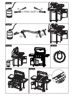
Страница 20: ... and that the hose does not come into contact with the heat shield or the grill head Set the LP tank into the hole in the bottom shelf Make sure the threaded connection at the top points toward the rear of the grill as shown in Fig 9 Secure the tank in place with the tank hold chain as shown in Fig 9 Fig 9 20 ...

Страница 21: ...e protective cap from LP tank valve Always use cap and strap supplied with valve 5 Inspect valve connection port and regulator assembly Look for any damage or debris Remove any debris Inspect hose for damage Never attempt to use damaged or plugged equipment Contact your local LP gas dealer for repair 6 When connecting regulator assembly to the valve hand tighten nut clockwise to a positive stop as...

Страница 22: ... area NEVER fill the tank beyond 80 full An overfilled spare LP tank is dangerous because surplus gas may leak from the safety relief valve The safety relief valve on an LP tank could activate to release gas and cause a fire Place dust cap on cylinder valve outlet whenever the cylinder is not in use Only install the type of dust cap on the cylinder valve outlet that is provided with the cylinder v...

Страница 23: ...appliances and flammable materials 6 Keep grill away from open flames and or sparks while testing TO TEST 1 Make sure all control knobs are in the OFF position 2 Make sure the regulator is connected tightly to the LP tank 3 Completely open LP tank valve by turning counterclockwise If you hear a POP sound turn gas off IMMEDIATELY because it indicates a heavy leak at the connection Call your gas dea...

Страница 24: ...NSTRUCTION VERY IMPORTANT ALWAYS INSPECT THE HOSE PRIOR TO EACH USE BEFORE LIGHTING Inspect the gas supply hose before turning the gas ON If there is evidence of cuts wear or abrasion it must be replaced before use The replacement hose assembly must be that specified by the manufacturer TO LIGHT MAIN BURNERS OF THE GRILL Read instructions before lighting _ 1 Open the lid and make sure all knobs ar...

Страница 25: ...sage 1 Read instructions before lighting 2 Open the lid and remove the cooking grids during lighting 3 Turn a control knob to the ignite position _ as shown in Fig 12 4 Remove match holder from knot on side of base Place a lighted match between the coils on the end of the match holder and hold next to the burner to ignite as shown in Fig 12 If ignition does not occur in 5 seconds turn the burner c...

Страница 26: ...ER use in a enclosed area such as a carport porch covered patio garage or under a surface that can catch fire Do not block the ventilation holes in the four sides of the grill cart since it may affect the combustion performance of the burner due to insufficient air Use the grill at least 36 91 cm away from any wall or surface and 120 305 cm away from objects that may spark and ignite gas i e live ...

Страница 27: ...ds cooked for a long time or basted with a sugary marinade may need a lower heat setting near the end of the cooking time 1 Make sure the grill has been leak tested and is properly located 2 Remove any packing material 3 Light the grill burners using the instructions in this manual 4 Turn the control knob to HI and preheat the grill for 15 minutes or to desired temperature 5 The grill lid is to be...

Страница 28: ...rted must have a safety cap 9 Never leave an LP tank in a recreational vehicle or boat which may become overheated by the sun 10 Do not store LP tank in or near an area where children play 11 For any other problems see Troubleshooting or contact Consumer Affairs CARE AND MAINTENANCE MAINTENANCE 1 Keep the grill area clear and free from combustible materials gasoline and other flammable vapors and ...

Страница 29: ...f insects or other obstructions are blocking the flow of gas through the burner you wilt need to call Consumer Affairs VERY iMPORTANT The orifice of the valve must be located in the center of the burner section after removal and cleaning Otherwise it may cause serious bodily injury and property damage Swing the burner slightly after replacing to check whether it has been installed properly GREASE ...

Страница 30: ...Burner or orifice blocked Low gas pressure Grill not preheated Excessive meat fat Temperature too high Grease deposit High winds Gas pressure too high Burner port blocked Grease accumulated in food SOLUTION Refill or replace propane tank Use clean swab and alcohol to clean Replace Reconnect or replace with new igniter assembly with wires Check the orifice for blockage Replace with new igniter asse...

Страница 31: ...ature of the meat if necessary 6 Place cooked foods and leftovers promptly into the refrigerator when done eating VERY IMPORTANT DO NOT LEAVE THE GRILL UNATTENDED WHILE COOKING GRILL STORAGE 1 Clean the grill Turn the gas off at the supply cylinder 2 Store the grill in a well ventilated dry outdoor area Keep out of the reach of children when LP tank is connected to the grill 3 Store the grill indo...

Страница 32: ...is warranty extends only to the original consumer purchaser Keep the original sales receipt as proof of purchase is required to make a warranty claim This warranty is void if the product is used for other than single family household use such as commercial or rental uses We exclude all claims for special incidental and consequential damages caused by breach of express or implied warranty All liabi...

Страница 33: ...ERO ESTE MANUAL A FiN DE OBTENER INSTRUCCIONES IMPORTANTES DE DESEMPAQUE Y MONTAJE Parri a Manual Asuntos del a Gas Tipo OG01 de Montaje y Operaci6n Consumidor 1 800 851 8900 SOLO PARA USO EN EL EXTERIOR Hamilton Beach Brands Inc Glen Allen Virginia 23060 33 ...

Страница 34: ... de Operaci6n 59 Consejos de Seguridad 61 Cuidado y Mantenimiento 62 Resolviendo Problemas 64 Seguridad de los Atimentos 66 Almacenamiento de la Parritla 66 Si huele gas 1 Corte la conexi6n de gas a la parrilla 2 Apague cualquier llama abierta de inmediato 3 Abra la tapa de la parrilla 4 Si el olor continua al_jese de la parrilla y Ilame inmediatamente al proveedor de gas o al departamento de bomb...

Страница 35: ...e instalarse dentro o sobre vehfculos recreativos o barcos NOTA AL INSTALADOR Deje este manual del usuario al consumidor despues de la entrega y o instalaci6n NOTA AL CONSUMIDOR Deje este manual de usuario en un lugar conveniente para referencia futura S MBOLOS DE SEGURIDAD Los sfmbolos listados aquf se utitizan en todo el manual Preste especial atenci6n a los mismos El significado de cada uno de ...

Страница 36: ...ido y rotutado de acuerdo con las especificaciones para tanques de gas LP det Departamento de Transporte de los EE UU DOT o la Norma Nacional de Canad CAN CSA B339 Tanques esferas y tubos para el transporte de materiales peligrosos Si se utiliza una fuente etectrica externa e aparato a gas para cocci6n at aire Nbre cuando se instale debe conectarse a tierra de acuerdo con los c6digos locales o si ...

Страница 37: ...90127800 10 Bandeja de Calentamiento 1 990127900 11 Rejitla de Cocci6n 2 990128000 12 Difusor de Calor Difusor de 3 990128100 Llamas 13 Quemador Principal 3 990128200 14 Colector Quemador Principal 1 990128300 15 V_ttvula de Gas Quemador 3 990128400 Principal 16 Reg ulador 1 990129700 17 Panel de Control 1 990130200 18 Perilta de Control 3 990128500 19 Panel Trasero 1 990139500 20 Estante Lateral ...

Страница 38: ... Izquierdo 1 990130300 26 Soporte para Portaceriltos 1 990137000 Nudo de Nylon 27 Portaceriltos 1 990137100 28 Deflector del Tanque 1 990139600 29 Panel Derecho 1 990135600 30 Panel Frontal 1 990130000 31 Estante Inferior 1 990129800 32 Rueda Normal 2 990128900 33 Pata 2 990129000 38 ...

Страница 39: ...DIAGRAMA DE PIEZAS DE LA PARRILLA J J I I i I 39 ...

Страница 40: ... cortando los bordes con un cortador de cajas Quite todas las piezas del poliestireno de protecci6n como se indica en la Fig A Quite todas las piezas de las bolsas pla sticas Cabezal de la Parrilla Estante inferior Bandeja de Calentamiento Panel Frontal Panel Derecha y Izquierda Cabezal de la Parrilla Deflector del Tanque Armaz6n del Carrito Poliestireno Fig A 40 ...

Страница 41: ...paque y saque todas las piezas de las cajas como se indica a continuaci6n en la Fig B Cabezal de la Parrilla Rejilla de Cocci6n Poliestireno Puerta y Derecha Estante Difusor Calor Caja _ Herramientas el Gancho del _ _ Paquete Grasa y Recipiente _i _ _ D_ _a_a para Grasa d t _ _ Cadena de Sujeci6n J _ del Tanque Ruedas Calibrador de Posici6n Fig B 41 ...

Страница 42: ...ador de estrella 2 no provisto Las siguientes herramientas se incluyen en el paquete de protecci6n M4 x 10 Tornillos 16 M5 x 10 Tornillos 5 M6 x 26 Tornillos 2 M6 x 13 Tornillos 16 M6 Arandela de Plana 4 M6 Arandela de Compresi6n 2 Llave 1 M4 Nuez 4 Soporte para Portaceriltos Nudo de Nylon 1 Portaceritlos 1 42 ...

Страница 43: ...erior a mano utilizando et calibrador de posici6n para determinar la profundidad adecuada como se indica en ta Fig 1 Una vez que la pata se ha atornillado a la profundidad adecuada sostengala en su lugar mientras ajusta la tuerca al estante inferior con la Itave provista como tambien se indica en la Fig 1 Esto asegurarb la pata en su lugar 3 Repita el paso 2 con la otra pata Calibrador de posici6n...

Страница 44: ...llos M5 x 10 como se indica en la Fig 2 3 Sujete el panel izquierdo marcado L at panel frontal con tres 3 tornillos M4 x 10 como se indica en la Fig 2 Sujete el panel izquierdo al estante inferior con un 1 tornillo M5 x 10 como se indica en la Fig 2 4 Sujete el panel derecho marcado R at panel frontal con tres 3 tornitlos M4 x 10 Sujete el panel derecho al estante inferior con un 1 tornillo M5 x 1...

Страница 45: ... al estante inferior con dos 2 tornillos M6 x 13 1 en cada lado como se indica en la Fig 3 4 Coloque los extremos del deflector det tanque de modo que los orificios de los extremos del deflector se encuentren alineados con los orificios de los paneles laterates luego sujete el deflector det tanque a los panetes izquierdo y derecho con cuatro 4 tornillos M4 x 10 2 en cada lado desde la parte exteri...

Страница 46: ...n cuidado baje el cabezal de la parritta sobre el carrito Verifique que la manguera del regulador se encuentre colgando fuera del carrito Sujete el cabezal al carrito con dos 2 tornillos M6 x 13 y dos 2 arandelas planas M6 en el frente dos 2 torniltos M6 x 26 en la parte trasera como se indica en la Fig 4 0 La manguera del regulador debe guiarse fuera del carrito Fig 4 46 ...

Страница 47: ...cocci6n de la ca mara de combusti6n 2 Desde la parte exterior de la cb mara de combusti6n sujete el estante derecho marcado R con dos 2 tornillos M6 x 13 y dos 2 arandelas planas M6 como se indica en la Fig 5b 3 Desde la parte interior de la camara de combusti6n sujete el estante derecho con dos 2 tornillos M6 x 13 y dos 2 arandelas de compresi6n M6 como se indica en la Fig 5c 4 Repita los pasos a...

Страница 48: ...PASOS DEL MONTAJE PASO 5 Estante de Lados I jjJ Fig 5b Fig 5c 48 ...

Страница 49: ...echo luego coloque el portaceritlos dentro de 61y captOrelo como puede verse en la Fig 6 U _ J _ _ PASO 7 Recipiente para Grasa 1 Cotoque el recipiente para grasa dentro det gancho del recipiente para grasa y cuelguelo desde la parte inferior de la ca mara de combusti6n como se indica en la Fig 7 Fig 7 49 ...

Страница 50: ...ti6n como se muestra en las Fig 8b y Fig 8c 2 Coloque las rejillas de cocci6n sobre los soportes de las rejillas como se indica en la Fig 8a 3 Introduzca la bandeja de catentamiento en la parte superior de la ca mara de combusti6n como se muestra en la Fig 8a Fig 8a Frente de los difusores de caior 50 Parte trasera de los difusores de caior Visi6n desde la parte trasera de la c_mara de combusti6n ...

Страница 51: ...l transporte de materiales peligrosos Ver el coltarfn del tanque de LP para verificar los r6tutos 4 El tanque debe estar orientado de modo de brindar una eliminaci6n de vapor adecuada como se indica en la Fig 9 5 Debe incluir un cotlarfn para proteger la va lvuta det tanque 6 No debe tenet abotladuras u 6xido Un tanque de LP con aboltaduras u 6xido puede ser peligroso y su proveedor debe controlar...

Страница 52: ...n contacto con la protecci6n termica o el cabezal de la parrilta Coloque el tanque de LP en et orificio del estante inferior Verifique que la conexi6n roscada de la parte superior apunte hacia la parte trasera de la parrilla como se indica en la Fig 9 Fije el tanque en su lugar utilizando la cadena de sujeci6n del tanque como se indica en la Fig 9 Fig 9 52 ...

Страница 53: ... 4 Quite la tapa protectora de la va lvula del tanque de LR Siempre use la tapa y abrazadera suministradas con la va tvuta 5 Inspeccione la boca de conexi6n de la vatvuta y el montaje de regutador Verifique que no haya da_os o residuos Quite los residuos Inspeccione la manguera en busca de dafios Nunca intente utilizar equipamiento da_ado o tapado Comunfquese con su proveedor local de gas LP para ...

Страница 54: ... Un tanque de LP de repuesto que supera su capacidad de Ilenado es peligroso porque el gas excedente puede escaparse de la va lvuta de alivio de seguridad La valvula de alivio de seguridad del tanque de LP puede activarse liberar gas y provocar un incendio Coloque una tapa guardapolvos en la salida de la vb tvula del tanque cuando este no se encuentre en uso S61o instale la clase de tapa guardapol...

Страница 55: ... de llamas abiertas y o chispas durante la prueba PARA EFECTUAR LA PUESTA A PRUEBA 1 Verifique que todas las periltas de control se encuentren en la posici6n OFF apagado 2 AsegOrese de que et regutador este conectado firmemente al tanque de LR 3 Abra pot completo la va tvula del tanque de LP girando en sentido contrario alas agujas del reloj Si oye un sonido fuerte PUM apague et gas DE INMEDIATO p...

Страница 56: ...ro de la secci6n det quemador despues de la remoci6n y limpieza De otro modo puede provocar graves lesiones corporales y dafios a la propiedad Balancee el quemador ligeramente despues de volver a colocarlo para verificar que se haya instalado correctamente Las perillas deben girar libremente El regutador y la manguera conectados a la parritla deben ser provistos por et fabricante predeterminado pa...

Страница 57: ...entren en la posici6n OFF apagado 2 Presione y gire la perilta lentamente en sentido contrario alas agujas del reloj para encender como se se_ala en la Fig 11 ContinOe presionando hasta que el quemador se encienda luego libere Repita para los otros quemadores 3 Si el quemador no se enciende inmediatamente gire la perilla de control a la posici6n OFF apagado y repita el paso 2 Fig 11 4 Si et quemad...

Страница 58: ... estante del lado derecho Uso 1 Lea las instrucciones antes del encendido 2 Abra la tapa durante el encendido 3 Gire la perilta de control a la posici6n de encendido como se indica en la Fig 12 4 Quite el portaceriltos del nudo en el costado de la base Coloque un cerillo encendido entre las bobinas en el extremo del portacerillos y sostenga at lado del quemador para encender como se muestra en la ...

Страница 59: ...L AIRE LIBRE NUNCA la utilice en un a rea cerrada como una cochera abierta porche patio cubierto garaje o debajo de una superficie que pueda prenderse fuego No bloquee los orificios de ventilaci6n ubicados en los costados del carrito de la parrilla porque puede afectar la combusti6n del quemador debido a una presencia insuficiente de aire Utitice la parrilla a por Io menos 36 91 cm de cualquier pa...

Страница 60: ...ar una configuraci6n de calor mb s baja cerca de la finalizaci6n del tiempo de cocci6n 1 Verifique que se haya efectuado la prueba de perdidas de gas en la parrilta y que esta se encuentre correctamente ubicada 2 Quite cualquier material de empaque 3 Encienda los quemadores de la parritta utilizando las instrucciones de este manual 4 Gire la perilla de control a la configuraci6n ma s alta posible ...

Страница 61: ...nstataci6n de tapones de v lvula roscados ajustados firmemente y no deben almacenarse en un edificio garaje o cualquier otra clase de a rea cerrada 6 Apague todas las periltas de control y la va lvula del tanque de LP cuando no utilice la parrilla 7 Si el artefacto se almacena en el interior el tanque de LP debe desconectarse y quitarse de la parritta 8 Los tanques de LP deben almacenarse at aire ...

Страница 62: ...res de la siguiente manera Quite las rejillas de cocci6n y los difusores de calor Encienda los quemadores Gire las periltas de la configuraci6n mb s alta a la mb s baja y controle el estado de las llamas La llama en la posici6n mb s baja debe ser m_ s peque_a que en la posici6n m_ s alta como se indica en la figura de abajo Siempre verifique la llama antes de cada uso Vet Resolviendo Problemas si ...

Страница 63: ...insectos u otras obstrucciones bloqueando el flujo de gas a traves det quemador usted deberb Itamar a Asuntos de Consumidor MUY IMPORTANTE El orificio de la v_tlvula debe colocarse en el centro de la secci6n del quemador despues de la remoci6n y limpieza De otto modo puede provocar graves lesiones corporales y dafios a la propiedad Balancee et quemador ligeramente despues de volver a colocarlo par...

Страница 64: ... cables del encendedor Vuelva a conectar o reemplace con esta n flojos o se han un nuevo montaje de encendedor caido con cables El orificio esta bloqueado Controle que el orificio este libre de bloqueos El cable ha sufrido un cortocircuito No hay gas Reemptace con un nuevo montaje de encendedor con cables Abra la vatvuta del tanque de LP o cambie la va lvuta del tanque de LR El flujo de gas no es ...

Страница 65: ...umutaci6n de grasa en los aNmentos Extinci6n de las llamas Las llamas se elevan Presi6n del gas muy elevada Retroceso de la llama Boca del quemador Limpie la boca del quemador bloqueada Incendio por grasa Limpie Encuentre un lugar menos ventoso Llame al proveedor de gas Apague todas las periltas y la va lvuta del tanque de LR Deje la tapa abierta y deje que el fuego se consuma Limpie la parriNa de...

Страница 66: ... inspeccionar la temperatura interna de la came si fuera necesario 6 Coloque los alimentos cocidos y los restos ra pidamente dentro del refrigerador cuando haya finalizado de comer ALMACENAMIENTO DE LA PARRILLA 1 Limpie la parrilla Apague et suministro de gas desde el tanque 2 Almacene la parrilta en un rea al aire libre seca y bien ventilada Mantenga fuera del alcance de los nifios cuando el tanq...

Страница 67: ...67 ...

Страница 68: ...ia se extiende s61o al comprador original Conserve el recibo de venta original ya que se requiere una prueba de compra para poder efectuar un reclamo de garantia Esta garantia pierde su validez si el producto se utiliza para un objetivo diferente del uso de una vivienda unifamiliar como fines comerciales o de alquiler Excluiremos todas las reclamaciones por da_os especiales incidentales o consecue...

Отзывы: