


14
2000225008D
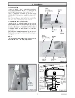
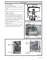
Diagram 4.12
FRONT AIR PRESSURE
SWITCH TUBE (CLEAR)
ELECTRICAL
CONNECTORS
REAR AIR PRESSURE
SWITCH TUBE (RED)
4 Installation
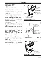
4.8 Flue / Boiler Connection
Remove the three self-tapping screws from the lower part of the
control box support bracket, see diagram 4.10.
Undo the wing nut that secures the top of the heat shield and
carefully hinge down control box and heat shield, see diagram
4.10.
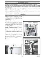
Release the toggle latches that secure the fan access door and
remove, see diagram 4.11.
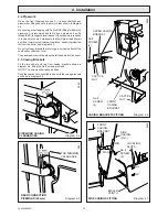
Remove the electrical connections from the fan by pulling the
insulation boots only and disconnect the air pressure tubes from
the fan taking note of their positions, see diagram 4.12.
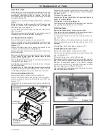
Remove the fan assembly from the flue hood by removing the
securing screw, pull forward and lift up to release the 3 hooked
securing lugs underneath the fan, see diagrams 4.12 & 4.13.
From the Chimney Flue Adapter Kit take the flue spigot, the
gasket is supplied in the fittings pack.
Connect the flue spigot and gasket to the top flue outlet of the
boiler using the self tapping screws provided, see diagram 4.14.
From the Chimney Flue Adapter Kit, take the chimney flue
adapter and remove restrictor securing screw, select and fit
appropriate restrictor :
Marked 'C'
then secure in place with the previously removed screw. To
connect a condensate drain, remove plastic end stop by
depressing the collet.
Slide the Chimney Flue Adapter into the flue spigot until it
engages in the bayonet connection, then twist clockwise to lock,
see diagram 4.14.
Rest the flue duct extension on the support bracket and engage
into the chimney flue adapter, see diagram 4.15. Refit fan
ensuring it is engaged into the flue duct extension and the
securing lugs are located correctly into the flue hood, secure
with fan securing screw. Replace electrical connections and air
pressure tubes.
The polarity of the electrical connections is not important.
Make sure that the air pressure tubes are fitted as before, see
diagram 4.12 and that the fan duct engages fully into the flue
duct extension piece.
IMPORTANT. With regards to the Manual Handling Operations,
1992 Regulations, the following operation exceeds the
recommended weight for one man lift.
Place the boiler in position taking care not to damage the casing
panels.
Flue Connection
NOTE: Fix and seal the flue to the hood of the chimney flue
adapter in accordance with normal practice.
The flue should be 125mm (5in) nominal diameter, refer to
section 3.
Diagram 4.13
SECURING
LUGS
Diagram 4.11
TOGGLE
LATCHES
FAN
ACCESS
DOOR
AIR
PRESSURE
TUBE (RED)
10259
FAN
SECURING
SCREW