HALE UMC32+ Скачать руководство пользователя страница 3


UMC32+ DIY USB-MIDI User Manual


Firmware v3.1.0, Hardware v1.1, Datasheet: 03/20/2011 1:37 PM  /   © 2008-20011 Hale Microsystems LLC, http://www.halemicro.com 


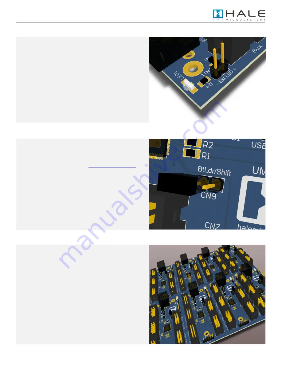
Status Indicator LED (CN11) 


The  indicator  LED  (LED1)  can  be  found  next  to  the  USB 
connector.  This LED provides information about the state of the 
UMC.  When connected, your computer will recognize the UMC 
and load the class compliant USB-MIDI class device driver that 
is provided by your operating system.  The LED will stay on until 
communication with your host application begins.  At this point 
the  LED  will  flicker  when  MIDI  traffic  between  the  host 
application and the UMC occurs.   
 
The  UMC32+  also  provides  a  2  pin  header  +  (Anode)  and  – 
(Cathode) for connecting to an external LED.  It is important to 
remember that in an addition to the LED itself, you will need to 
provide a current limiting resistor in series with your LED (Less 
than 20mA is recommended at 5V dc). 


Boot Loader / Shift Pin (CN9) 


When the UMC is plugged into the USB port it first checks the 
state of the shift pin, if it is pulled low (your switch is being held) 
then the UMC will enter bootloader mode and prepare to accept 
a firmware update. Information regarding firmware updates will 
be made available on our website at 

http://www.halemicro.com 

 
In  response  to  customer  requests  there  have  been  many 
revisions to the UMC firmware.  It is important that you ensure 
that you are reviewing the correct manual that corresponds with 
the firmware version of your device. 
 
During normal MIDI operation this pin can double the number of 
software parameters you can control.  See Hardware I/O Types 
For more information 


Multiple UMC’s using a USB Hub 


For connecting more than 1 UMC32+ to the same computer it is 
recommended  that  you  install  one  of  8  available  firmware 
binaries  on  your  UMC32+.    First  download  the  latest  firmware 
set  from  the  Hale  website.    The  zip  file  will  contain  multiple 
firmware revisions with “.DLD” extensions.  Next download and 
install  the  UMC32+‟s  firmware  update  utility,  follow  the 
directions  provided  by  the  utility  and  select  the  appropriate 
firmware.  Each  firmware  binary  is  slightly  different  in  that  they 
contain  a  unique  USB  product  ID  as  well  as  a  unique  driver 
name that allows the operating system to identify it on the USB 
bus.  As a rule of thumb it is recommended that when you are 
configuring  your  device  using  the  Configuration  Utility  you 
dedicate  one  MIDI  channel  to  each device  (2  MIDI  channels  if 
you are using the shift feature).  As MIDI host applications and 
operating  system  do  not  always  load  and  assign  UMCs  in  the 
same  order  this method  has  proven  to  be  a  consistent  way  of 
identifying each UMC that is connected to your system. 


Содержание UMC32+

Страница 1: ...UMC32 DIY USB MIDI Controller USER MANUAL Firmware v3 1 0 Hardware v1 1 2008 2011 Hale Microsystems LLC All Rights Reserved...

Страница 2: ...O s corresponding MIDI message value o Individual selection of each I O s corresponding MIDI message type s Note On Poly Pressure Controller Individual selection of each I O s corresponding hardware t...

Страница 3: ...w halemicro com In response to customer requests there have been many revisions to the UMC firmware It is important that you ensure that you are reviewing the correct manual that corresponds with the...

Страница 4: ...B Power CN10 The factory default has CN10 fitted with a jumper to provide power via the USB bus This also provides a convenients means for measuring the current consumption of your final build The onl...

Страница 5: ...and Windows 7 it will show up as UMC32 _D0x where x is the device number The device number you see will depend on the firmware that you have bootloaded into the UMC All devices are shipped from the f...

Страница 6: ...u happen to solder the 5V and Ground terminals on a potentiometer backwards Instead of reopening your device to correct the problem by resolder again simply select this mode instead IN Analog Average...

Страница 7: ...hat you observe some simple guidelines when working with the UMC Failure to do so may cause damage to your equipment and or void your product warranty o Treat the UMC32 as you would any modern compute...

Страница 8: ...LLC http www halemicro com 8 Example Connections Although there are a seemingly infinite number of types of control elements potentiometers switches etc that you can connect to the UMC here are a few...

Страница 9: ...irmware v3 1 0 Hardware v1 1 Datasheet 03 20 2011 1 37 PM 2008 20011 Hale Microsystems LLC http www halemicro com 9 UMC32 I O Pin Diagram UMC32 in picture above with attached ribbon cable Ribbon cable...

Страница 10: ...hes on the Aux inputs 8 from master 8 from slave This provides a total of 80 controls using a single bus powered USB connector Linker board in center connects the UMC s together Using multiple process...

Страница 11: ...ng holes for the UMC32 are for 4 screws USB Connector measurments millimeters Electrical Specifications Exceeding the absolute maximum ratings below may cause permanent damage to the device Storage te...

Страница 12: ...t shall void this warranty Disclaimer Neither the whole nor any part of the information contained herein or the product described in this datasheet may be adapted or reproduced in any material or elec...

Отзывы: