9. Drive
Sheet 83
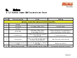
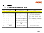
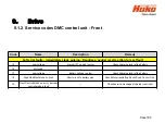
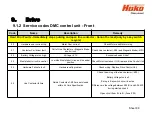
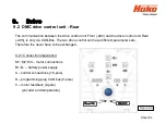
The drive control features its own diagnostics and a self-test.
Therefore, the function of the drive control unit is locked when turning on the
machine if the speed control potentiometer isn´t in neutral or is not recognised
as being in neutral position.
The same behaviour applies after the seat contact switch has opened and is
closed again.
The speed control potentiometer must also be in neutral when the seat contact
switch is closed, or to be more precise it must be detected as being in neutral
by the drive control unit.
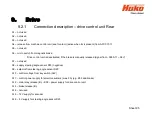
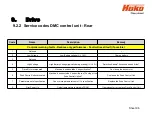
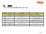
If the drive control unit does not recognise that the speed control potentiometer
is in neutral, it shows flashing signals (LED) at the drive control unit.
These messages are transferred to the machine control unit via the CAN bus,
where they are evaluated. For front- and Rear drive motor, different drive
control modules are used. The drive control units must not be mixed up.
Содержание Scrubmaster B175 R
Страница 37: ...3 Technical Data Sheet 37...
Страница 38: ...3 Technical Data Sheet 38...
Страница 39: ...3 Technical Data Sheet 39...
Страница 40: ...3 Technical Data Sheet 40...
Страница 41: ...3 Technical Data Sheet 41...
Страница 42: ...3 Technical Data Sheet 42...
Страница 43: ...3 Technical Data Sheet 43...
Страница 44: ...3 Technical Data Sheet 44...
Страница 46: ...4 1 Hako System Maintenance customer Sheet 46...
Страница 47: ...4 1 Hako System Maintenance customer Sheet 47...
Страница 48: ...4 2 Hako System Maintenance I Sheet 48...
Страница 49: ...4 2 Hako System Maintenance I Sheet 49...
Страница 50: ...4 2 Hako System Maintenance I Sheet 50...
Страница 51: ...4 3 Hako System Maintenance II Sheet 51...
Страница 52: ...4 4 Hako System Maintenance III S Safety Check Sheet 52...
Страница 65: ...6 Machine settings 6 1 6 Charging characteristics for integrated charger Sheet 65...
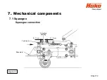
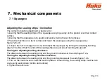
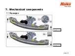
Страница 74: ...7 Mechanical components Figure 7 2a Figure 7 2b Sheet 74 7 1 Squeegee...
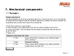
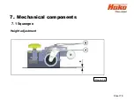
Страница 76: ...7 Mechanical components Height adjustment Figure 7 4 Sheet 76 7 1 Squeegee...
Страница 104: ...9 Drive 9 2 4 Steering angle sensor Figure 9 5 180 130 170 150 120 Folie 104...
Страница 112: ...10 2 Service alarm clock 3 3 1 1 Sheet 112 The service alarm clock is set via the Hako diagnostic system...
Страница 113: ...11 Battery charger 11 1 Operating manual Sheet 113...
Страница 114: ...11 Battery charger Sheet 114 11 1 Operating manual...
Страница 115: ...11 Battery charger Sheet 115 11 1 Operating manual...
Страница 116: ...11 Battery charger Sheet 116 11 1 Operating manual...
Страница 123: ...13 Notes Sheet 123...
Страница 124: ...Sheet 124 13 Notes...

