

Troubleshooting guide
For details, refer to the instruction manual for the station with which the
unit will be used.
The solder clogs.
ACTION : Do not pull solder from a heavy reel with the trigger. Keep the
solder loose (without tension) on the solder inlet side at all
times while soldering.
ACTION : Refer to “Inserting the solder” under “Operation.”
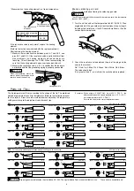
Checking for breakage of the heating
element and cord assembly
Disconnect the plug and measure the resistance between the
connecting plug pins as follows.
3
1
2
4
5
a. Between pins 4 & 5
(Heating element)
b. Between pins 1 & 2
(Sensor)
c. Between pin 3 & tip
2.5 – 3.5
(Normal)
43 – 58
(Normal)
under 2
If the values of ‘a’ and ‘b’ are outside the above value, replace the heating
element (sensor) and /or cord assembly.
If the value ‘c’ is over the above value, remove the oxidization film by
lightly rubbing with sand-paper or steel wool the points shown below.
Rub lightly
Broken heating element
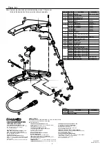
Disassembling the 951/952
1. Remove the adjusting screw and keep the support fitting apart
from the housing.
2. Turn the nut counterclockwise and remove the tip enclosure ,
the tip .
CAUTION
Be sure to remove the nut before removing the nipple. Removing the nipple
first could cause the heater leads to twist and cause a short circuit.
3. Turn the nipple counterclockwise and remove it from the gun.
4. Remove the 4 screw securing the housing and open the housing.
5. Pull the grounding spring out of the sleeve.
1
2
Nut
Tip enclosure
3
Tip
4
5
Nipple
Grounding
spring
2
Part Name
Solder inlet
Tip
Guide nozzle
Cord assembly
Support fitting
Adjusting screw
Trigger
Plug
Solder feed
adjusting screw
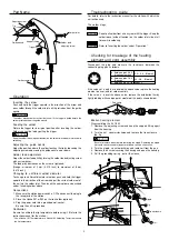
Operation
Inserting the solder
Push and hold the trigger upward in the direction of the arrow and
pass solder through the solder inlet until it protrudes from the guide
nozzle.
CAUTION
The solder may become stuck inside the unit if the trigger is pulled before the
solder protrudes from the guide nozzle.
Feeding the solder
Return the trigger to its original position after inserting the solder.
Solder can now be fed by pulling the trigger.
CAUTION
Keep the solder loose (without tension) on the solder inlet side at all times while
soldering.
Adjusting the guide nozzle
Adjust the position where the solder touches the tip by loosening the
adjusting screw and moving the guide nozzle up or down.
Solder feed adjustment
Adjust the solder feed pitch by turning the solder feed adjusting screw
with a screwdriver.
The feed pitch decreases as the screw is tightened.
(Range: minimum of 2 mm (0.079 inch) to maximum of 8 mm
(0.315 inch))
Changing to a different solder diameter
To change to a different diameter of solder, push and hold the trigger
upward in the direction of the arrow and pull the current solder out of
the unit via the solder inlet. Then insert the new solder as described
under “Inserting solder” above.
Connections
1. Make sure the station power switch is OFF and connect the plug to
the receptacle of the station.
2. Place the Hakko 951 or 952 on the iron holder (optional).
3. Plug the power cord into a grounded wall socket.
Be sure the unit is grounded.
Calibration
Be sure to calibrate the tip temperature before using it. (Refer to the
instruction manual for the station.)
* Use a Hakko 191 Thermometer or a Hakko 192 Soldering Tester to measure
the tip temperature.


