background image

96 (97) 

Hakki Pilke 42 Easy 

Original   

Version 5 


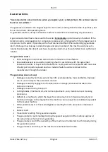
Guarantee terms 


“Guarantee terms come into force when you register your customership in the extranet service 
found on our website.” 


The guarantee is valid for the original buyer for 12 months, starting from the date of purchase, but 
for no more than 1 000 operating hours. 
In guarantee matters, always contact the machine’s seller before undertaking any procedures. 
 
A guarantee demand has to be issued to the seller 

immediately

 upon discovery of a defect. If the 

defect concerns a damaged part or component, please send a photograph of the damaged part or 
component to the seller, if possible, so the fault can be identified. When submitting a guarantee 
claim, the buyer must always include the type and serial number of the machine and present a 
receipt that includes the date of purchase. Guarantee claims must be submitted to an authorised 
retailer. 


The guarantee covers 


Parts damaged in normal use due to faults in material or manufacture. 


Reasonable expenses caused by repairing a fault in accordance with the agreement 
between the seller or buyer and manufacturer. Faulty parts will be replaced with new ones. 
A faulty part or parts replaced due to a material fault should be returned to the 
manufacturer through the retailer. 
 

The guarantee does not cover 


Damages caused by normal wear and tear (for example blades, mats and belts), improper 
use or use contrary to the instruction manual 


Damages caused by negligence of maintenance or storage procedures detailed in the 
instruction manual 


Damages caused during transport 


Cutting blades, V-belts and oil, and normal adjustment, care, maintenance or cleaning 
procedures 


Defects in a machine to which the buyer has carried out or commissioned structural or 
functional changes to the degree that the machine can no longer be considered equivalent 
to the original machine 


Other potential costs or financial obligations resulting from the procedures mentioned 
above 


Indirect costs 


Travel costs resulting from guarantee repairs 


The guarantee for parts replaced during the guarantee period of the machine expires at 
the same time as the machine’s guarantee 


The guarantee is void if the ownership of the machine is transferred to a third party during 
the guarantee period 


The guarantee is void if any of the machine’s seals have been broken 


Содержание Easy 42 Series

Страница 1: ...the log splitter ENGLISH Hakki Pilke 42 EASY LOG SPLITTER Instructions for assembly operation and maintenance EU Declaration of Conformity Safety instructions List of spare parts Terms of guarantee V...

Страница 2: ...15 6 1 Lowering the input conveyor into the operating position 15 7 OUTPUT CONVEYOR 18 7 1 Lowering the output conveyor into the operating position 18 7 2 Lifting the output conveyor into the transpo...

Страница 3: ...hannel start the machine and rotate the cutting flange by lowering it 44 Note The right way 44 20 7 Sharpening the blade chain 45 20 8 Maintenance of the flange 45 20 8 Lubrication 46 20 11 1 Lubricat...

Страница 4: ...nt including the ground underneath is safe for the machine operator and environment The 42 hydro log splitter is designed for preparing firewood from pruned or processed wood such as billets The log s...

Страница 5: ...GER ZONE BEWARE OF THE CHAIN ONLY ONE PERSON AT A TIME IN THE WORK AREA SHUT DOWN BEFORE MAINTENANCE BEWARE OF MOVING PARTS RISK OF ENTANGLEMENT WITH THE CARDAN SHAFT RISK OF CRUSHING DO NOT GO UNDER...

Страница 6: ...y Original Version 4 READ THE MANUAL BEFORE USE USE PROTECTIVE EQUIPMENT USE PROTECTIVE EQUIPMENT ALWAYS GRAB A LOG BY THE SIDES MAX RPM Scale HYDRAULIC OIL LEFT ROTATION CHAIN OIL LIFTING POINT FOR F...

Страница 7: ...212 When viewed from the side the log splitter must be standing completely straight A tractor connected log splitter that is used for testing or log cutting splitting must rest on its own weight on l...

Страница 8: ...rsion 4 2 2 Dispose of the packaging in an environmentally responsible manner Figure 221 1 Mount the sawdust conveyor on the log splitter Figure 222 2 Mount the output conveyor crank Note the screw th...

Страница 9: ...nd safety instructions in this manual before operating the log splitter A tractor powered log splitter must be connected to a tractor at all times during use 3 1 Cardan shaft When connecting and using...

Страница 10: ...connect the log splitter to a defective device or part Carry out all connection procedures thoroughly and carefully 3 2 Push bar and draw bars 3 3 Power cord of the electronic measuring device option...

Страница 11: ...ructions maintenance and safety insructions in this manual before operating the log splitter 4 1 Selecting the power source for a tractor and electrically powered combi log splitter Power source tract...

Страница 12: ...evers The green button is the Start button The red button is the Stop button Note The button must be in the UP position for the log splitter to start Turn the button slightly clockwise to lift it to t...

Страница 13: ...es on the control console at the front of the machine Figure 500 5 A External hydraulics connectors a1 a2 Maximum pressure 180 bar Operating lever J operating positions j1 j2 5 B Output conveyor and s...

Страница 14: ...splitting push the lever quickly to the left 5 E Foot switch e1 start splitting mode by pressing the foot switch down 5 F Start and stop an electrically powered log splitter f1 start the log splitter...

Страница 15: ...VEYOR 6 1 Lowering the input conveyor into the operating position Figure 611 6 1 1 Turn the winch crank B into the direction of the arrow enough to release the winch belt A some 10 cm 3 9 in NOTE Chec...

Страница 16: ...trong enough to bear the weight of the input conveyor The input conveyor is heavy and can cause permanent injury if it hits with full force The 42 Hydro log splitter is designed to be used by one pers...

Страница 17: ...Check that the input conveyor belt is tight enough before continuing The belt is tight enough if it rises about 2 cm 0 8 in from the middle 6 1 5 To lift the input conveyor to the transport and stora...

Страница 18: ...7 1 Lowering the output conveyor into the operating position Figure 711 7 1 1 Turn the winch crank B into the direction of the arrow enough to release the winch belt A some 10 cm 3 9 in Note Make sur...

Страница 19: ...8 ft 7 1 2 Grip the output conveyor handle C tightly with your left hand and lift the input conveyor locking handle d with your right hand Do not lift the locking handle too high up because it will l...

Страница 20: ...ly while turning the winch crank B until the belt is loose Figure 714 7 1 4 Check that the locking latch of the output conveyor s extension is not in the wrong position If the latch is visible use the...

Страница 21: ...t in the joint Always take extra care when working with the output conveyor Keep the conveyor area free of people and animals The conveyor must not be connected to the mains a tractor or any other pow...

Страница 22: ...in or similar as shown in the figure BE CAREFUL NEVER GO UNDERNEATH THE CONVEYOR 7 2 Lifting the output conveyor into the transport and storage position To lift the output conveyor into the transport...

Страница 23: ...olding was turned to the side in Chapter 7 1 6 When lifting you must first turn this lever against the output conveyor Figure 722 This prevents the belt from rolling down and being damaged Figure 723...

Страница 24: ...splitting guard must be up When the guard is up the log splitter cannot be used for splitting or cutting You can lift the guards from the lifting handles whenever necessary The log splitter stops auto...

Страница 25: ...position When the guards are in the operating position the log splitter can be used for cutting and splitting Figure 820 shows the lifting handles of the cutting and splitting guards as well as the ha...

Страница 26: ...s pin 9 2 Automatic measuring device The log splitter can be equipped with an optional optical freely adjustable measuring device for cutting logs Device parts Measurement adjustment Figure 922 Figure...

Страница 27: ...aulic lever 5C c2 p 12 You can increase and decrease the lowering force with a separate adjustment screw 5G p 12 The saw chain also stops when the splitting or cutting guard is lifted Figure 800 11 CO...

Страница 28: ...ted on the next page Figure 112 Splitting mode control lever positions You can use the splitting mode control lever to cancel splitting or to stop the cancelling Automatic set off as the splitting bla...

Страница 29: ...ce area The force range is from 3 to 12 tonnes The less force involved the faster the splitting motion 12 1 Automatic speed valve The splitting system is equipped with an automatic speed valve It decr...

Страница 30: ...ng the splitting blade STOP THE LOG SPLITTER BEFORE REPLACING THE SPLITTING BLADE WARNING HANDLE THE BLADE WITH CARE Note that the blade must not be down when you remove the locking pin 1 Lift the spl...

Страница 31: ...Chapter 4 2 Start and stop buttons Note When the surrounding temperature is below zero run the log splitter for a while without any testing procedures to increase the viscosity of the log splitter s h...

Страница 32: ...ice or wood residue between the conveyor and the ground If any exist it must be cleaned as often as necessary to ensure that they do not cause damage or dangerous situations when the log splitter is...

Страница 33: ...15 1 A 5 You have ensured that the air temperature cannot pose a risk to your health the snow or rain cannot pose a risk to your health or damage the log splitter the strong winds cannot pose a risk...

Страница 34: ...automatically WARNING When feeding logs to the cutter on the input conveyor make sure that the logs remain firmly on the conveyor Adjust the conveyor speed to a safe level When logs are fed to the cu...

Страница 35: ...at prevent normal splitting WARNING If a fallen log is in an imbalanced vertical or some other position that makes splitting impossible you must proceed as follows 16 1 1 Open the splitter guard 16 1...

Страница 36: ...ust be done so that it does not put the operator or machine at risk 16 2B Option B B1 Cancel the cutting by pushing the reversing lever quickly in the reverse position 5 d1 so that the splitting beam...

Страница 37: ...to make a whole piece of firewood leave the last full sized piece on the input conveyor and the undersized part on the splitting groove Cut the log When the last piece is on the input conveyor feed it...

Страница 38: ...input and output conveyors are in the transport position that the transportation height and width of the log splitter is safe so that it or the conveyors do not hit any buildings structure trees or si...

Страница 39: ...splitting guards are opened If the functions do not stop or start Determine the cause of the malfunction and if necessary contact the manufacturer or an authorised mechanic according to the terms of...

Страница 40: ...when processing wood make sure that there isn t any material on the wood that may damage the blade Always wear gloves when handling the blade WARNING Always hold the blade from the back and never fro...

Страница 41: ...and reduces machine power Adjusting the belt s tightness The tightness is adjusted with the screws at the end of the conveyor The correct position of the belt in relation to the frame and the folding...

Страница 42: ...r to check the tightness on both sides Make sure that the belt goes in the middle of the frame and the turnover rolls If the belt gets pulled to the side tighten it with the adjustment screw on the si...

Страница 43: ...yors side indicated by arrows and turn the blade guard to the position shown in the figure Disconnect the machine from the tractor and power supply Tightening Loosen the blade flange s fastening bolts...

Страница 44: ...to the flange fastening bolts and twist the bolts almost to the end 4 Tighten the chain sufficiently from the tightening bolt Figure 2061b 5 Tighten the fastening bolts of the flange sufficiently whil...

Страница 45: ...The file is too small The lowering measure is too big The lowering measure is too small The correct lowering measure is 0 65 mm Remember the correct filing direction When filing the chain and flange...

Страница 46: ...raulic filter is located next to the filling hole of the hydraulic oil behind the protective cage see Figure 20111 Change the hydraulic oil filter once every working season Order numbers 97348 Filter...

Страница 47: ...amount of oil released to the flange If the flange heats up and there is smoke when cutting wood add more oil If you can see oil splashing from the blade chain to the guards reduce the amount of oil 2...

Страница 48: ...down trigger bar Figure 2012b locks to the roll of the drive end white arrow Figure 2012a Figure 2017b Figure 2012c 2 Drive head up the trigger bar Figure 2012b lifts the starting lever 1C and the sta...

Страница 49: ...tion along with the trigger bar Figure 2012f and the slide has gone into motion 2012d Figure 2012f 2c The slide has reached its extreme position and the slide rod Figure 2012g has used the return shaf...

Страница 50: ...al Version 4 Figure 2012i 2d The slide has returned and the slide rod Figure 2012j has moved the push rod back to the initial position Figure 2012j the slide in its initial position Figure 2012k The i...

Страница 51: ...splitter pushing the ball shaft in If bars c1 and c2 are not tight enough level rod B does not turn far enough and the hydraulics of the machine do not work How to fix tighten the screws at the ends...

Страница 52: ...ld the stem of the valve with the other wrench c Twist the shaft with a hex key a of a turn at a time clockwise downwards in order to increase force Test If the force is still not enough add another o...

Страница 53: ...rce of the input conveyor Increasing the force of the input conveyor is carried out in the same way as that of the output conveyor see Chapter 20 15 The location of the adjustment valve is behind the...

Страница 54: ...al position of the splitting bar as well as the starting point of its reversal motion by adjusting the retainer bushing of the bar of the splitting motion guard behind the machine Figure 2017b B Adjus...

Страница 55: ...onditions Check 1st change Following X X X E g Teboil S 32 Oil filter Always when changing oil HEK02 20 201 AS RP025 VM B17 B Valve mechanism Lubrication X Lubrication oil spray All levers Lubrication...

Страница 56: ...56 97 Hakki Pilke 42 Easy Original Version 4...

Страница 57: ...57 97 Hakki Pilke 42 Easy Original Version 4...

Страница 58: ...58 97 Hakki Pilke 42 Easy Original Version 4...

Страница 59: ...59 97 Hakki Pilke 42 Easy Original Version 5 Power transmission combi of 42 hydro...

Страница 60: ...60 97 Hakki Pilke 42 Easy Original Version 5 Assembly of the angle transmission and hydraulic pump Combi...

Страница 61: ...61 97 Hakki Pilke 42 Easy Original Version 5 Power transmission of a tractor powered 42 hydro log splitter...

Страница 62: ...62 97 Hakki Pilke 42 Easy Original Version 5 Bearing housing and extension shaft of the electric motor combi...

Страница 63: ...63 97 Hakki Pilke 42 Easy Original Version 5 Assembly of the electric motor combi...

Страница 64: ...64 97 Hakki Pilke 42 Easy Original Version 5...

Страница 65: ...65 97 Hakki Pilke 42 Easy Original Version 5...

Страница 66: ...66 97 Hakki Pilke 42 Easy Original Version 5 Wood length limiter mechanical...

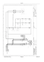
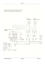
Страница 67: ...67 97 Hakki Pilke 42 Easy Original Version 5 Power transmission of an electrically powered 42 hydro log splitter...

Страница 68: ...68 97 Hakki Pilke 42 Easy Original Version 5...

Страница 69: ...69 97 Hakki Pilke 42 Easy Original Version 5...

Страница 70: ...70 97 Hakki Pilke 42 Easy Original Version 5...

Страница 71: ...71 97 Hakki Pilke 42 Easy Original Version 5...

Страница 72: ...72 97 Hakki Pilke 42 Easy Original Version 5...

Страница 73: ...73 97 Hakki Pilke 42 Easy Original Version 5...

Страница 74: ...74 97 Hakki Pilke 42 Easy Original Version 5...

Страница 75: ...75 97 Hakki Pilke 42 Easy Original Version 5...

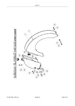
Страница 76: ...76 97 Hakki Pilke 42 Easy Original Version 5 Saw unit of 42 hydro...

Страница 77: ...77 97 Hakki Pilke 42 Easy Original Version 5 Assembly of the cutting in 42 hydro...

Страница 78: ...78 97 Hakki Pilke 42 Easy Original Version 5...

Страница 79: ...79 97 Hakki Pilke 42 Easy Original Version 5...

Страница 80: ...80 97 Hakki Pilke 42 Easy Original Version 5...

Страница 81: ...81 97 Hakki Pilke 42 Easy Original Version 5...

Страница 82: ...82 97 Hakki Pilke 42 Easy Original Version 5...

Страница 83: ...83 97 Hakki Pilke 42 Easy Original Version 5...

Страница 84: ...84 97 Hakki Pilke 42 Easy Original Version 5...

Страница 85: ...85 97 Hakki Pilke 42 Easy Original Version 5...

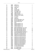
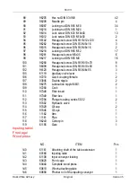
Страница 86: ...racket 2 19 60070 Reversing lever 1 20 60136 Cinder sheet 1 22 60320 Lever rod of the foot pedal 1 23 60330 Upper container 1 24 60350 Foot switch 1 25 60363 Idler 1 26 60367 Joint lever 1 27 60369 Co...

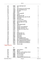
Страница 87: ...471 20 2 67 96079 Spring cotter DIN EN ISO 13337 8x60 2 68 96057 Bottom plate DIN EN ISO 7089 A8 28 69 96048 Bottom plate DIN EN ISO 7089 A10 44 70 96050 Bottom plate DIN EN ISO 7089 A12 45 71 96051...

Страница 88: ...ew DIN 933 M10x50 5 102 96120 Hexagonal screw DIN 933 M6x55 3 105 61119 Auxiliary valve lever 1 106 97210 Quick coupling female 2 107 03046 Double nipple 2 108 96275 Lubrication nipple M8X1 2 109 9728...

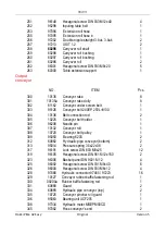
Страница 89: ...7 Hydraulic motor EPM160CD 2 185 97408 Hydraulic valve EASY VA 1 186 97427 Cartridge valve casing 97420 1 187 97533 Valve 1 188 97524 Valve 1 189 97061 Inputing table hose 1 190 97097 Inputing table h...

Страница 90: ...240EP 250L 8130 1 304 10136 Belt connection rod 2 305 10225 Conveyor belt holder 1 306 96208 Needle pin 1 307 10132 Conveyor roll 1 308 10720 Conveyor belt pulley 1 309 95050 Bearing 6205 2 312 60882...

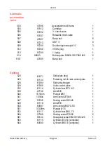
Страница 91: ...Stopper rod 1 477 10170 Bushing of valve operating rod 2 478 96228 Clamping screw DIN 913 M8x18 2 479 60769 Operating rod of releasing plate 1 480 61139 Releasing plate 1 481 60758 Connecting rod 1 4...

Страница 92: ...99 Banjo bolt 1 Splitting 520 61071 Slide plate top 1 523 61134 Fastening rod of valve control plate 1 528 61084 Slide attaching pin 1 529 61069 Valve control plate 1 532 61114 Cylinder liner 73 63 1...

Страница 93: ...ical wood measuring device NO 650 60650 Fastening pipe 1 651 47550 Wood measuring device 1 655 95197 Light cell 1 659 96312 Hex nut DIN 934 M4 2 660 96313 Bottom plate DIN 125 A4 2 662 95199 Reflectin...

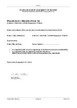
Страница 94: ...e person who is authorized to collect technical file Name Tapio Aittokoski Address Valimotie 1 85800 Haapaj rvi Finland Declares that Hakki Pilke 42 Easy Serial number is compatible with relevant regu...

Страница 95: ...6mm 0 63 Blade chain 71 loops 0 404 Hydraulic oil volume 65 l Maximum width in working position 9 5 m Input conveyor length 2 620 mm belt width 250 mm Dimensions in the transport position height 2 500...

Страница 96: ...between the seller or buyer and manufacturer Faulty parts will be replaced with new ones A faulty part or parts replaced due to a material fault should be returned to the manufacturer through the ret...

Страница 97: ...by the guarantee the manufacturer has the right to charge the customer for the pinpointing and possible repair of the fault or defect in accordance with the manufacturer s current price list This gua...

Отзывы: