22
4. Mechanical Instructions
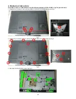
Note: May be there is a little difference for the following pictures with the LT42A1, only for your reference.
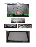
1. Unscrew the 5 screws in red to remove NECK COVER and STAND/BASE and as Fig 1.
Fig 1
2. Unscrew the 16 screws in red to remove REAR COVER and COVER IO and as Fig 2.
Fig 2
3. Disconnect all the WIRES in green as Fig 3.
Содержание LT42A1
Страница 24: ...24 Fig 5 6 Unscrew the 9 screws in red to remove STAND_BKT L R SPEAKER as Fig 6 Fig 6 7 The BEZEL ...
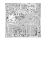
Страница 31: ...31 6 PCB Layout 6 1 Main Board 715G3431 1 ...
Страница 32: ...32 ...
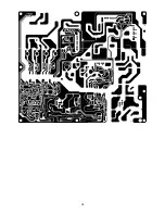
Страница 33: ...33 6 2 Power Board 715G3351 1 ...
Страница 34: ...34 ...
Страница 35: ...35 ...
Страница 36: ...36 715G3358 2 ...
Страница 37: ...37 6 3 Key Board 715G3293K01001004S 6 4 IR Board 715G3478R01002004M ...
Страница 39: ...39 8 Block Diagram ...
Страница 63: ...63 10 Exploded View ...

