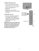
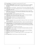
background image


19 

Hotel Mode(Option) 

Starting and Existing 


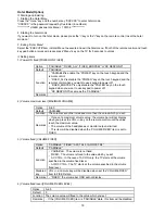
1. Starting the Hotel Menu   
Press the “menu” key and the number key “XXXXXX” to enter hotel mode. 
“XXXXXX” is the password request by Customer (6 numbers).   
************ HAIER password is Menu + 100108 *************   
 
2. Starting the hotel mode   
If you want to turn on the hotel mode, please press the“>”key or the“<”key on the remote control to set the hotel 
mode on


3. Exiting “Hotel Menu”   
Select the “EXECUTE”item in Hotel Menu to execute and exit the hotel menu. If both of the remote control and touch 
key pad button are locked, please press “Menu” key on the TV for 5 seconds to unlock. 
 

Setting items 


1) Power ON fixed [POWER ON FIXED] 


Option  

“VARIABLE”,“FIXED_ALL”,“FIXED_BODYKEY”or“RC RESPOND”   

Default   “VARIABLE”  

Function  

“VARIABLE”is enable the “POWER” key on the touch keypad and the 

remote control.   

“FIXED_ALL”is disable the “POWER” key on the touch keypad and the 

remote control when you want to use keypad to power off.   

“FIXED_BODYKEY”is only disable the “POWER” key on the touch 

keypad when you want to use keypad to power off.   

“RC RESPOND”is same as the “VARIABLE”.   

Remarks  


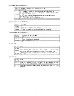
2) Volume maximum level [MAXIMUM VOLUME] 

Option  

0~60  

Default   VARIABLE  
Function    The volume cannot be increased more than the value which you set.   

Remarks 

If you set a maximum volume value, the volume bar will not display 

when you press the VOL +/- key on the remote control until the value 
reach the maximum value.   

The volume of the headphones or monitor output is limited.   

This item will be disabled when the “VOLUME FIXED” item is set to 

FIXED.  


3) Volume fixed [VOLUME FIXED] 
 

Option  

“VARIABLE”,“FIXED”,“ACCTRL”or“AC/RCCTRL”  

Default   “VARIABLE”  

Function  

VARIABLE

The volume is not fixed.   

FIXED

The volume is fixed to the value which you set.   

AC CTRL

In the case of AC ON only, the TV starts at the volume 

specified in the volume fixed level.   

AC/RC CTRL

The TV starts at the volume specified in the volume 

fixed level.   

Disabled 
key  

VOL +/- and mute key will be disabled when set the “VOLUME FIXED” 
item to FIXED state.   

Remarks  

“FIXED”, the volume bar OSD will not display.   

 
4) Volume fixed level [VOLUME FIXED LEVEL] 

Option  

0~60  

Default   0  
Function    The volume value will fixed to the value which you set.   
Remarks 

If the [VOLUME FIXED] item is “VARIABLE”state , this item will be disabled. 

Содержание LT19Z6

Страница 1: ...IS UNIT WHEN SERVICING 6 1 Main Board 40 6 2 Power Board 42 6 3 Key Board 49 6 4 IR Board 49 7 Adjustment 50 8 Block Diagram 52 9 Wiring Diagram 53 10 Schematic Diagram 56 10 1 Main Board 56 10 2 Power Board 69 10 3 Key Board 75 10 4 IR Board 76 Table of Contents 1 Important Safety Notice 2 Revision List 3 1 General Specification 4 2 Operating Instructions 5 2 1 The Use of Remote Control 5 2 2 To ...

Страница 2: ...cs might create shock fire or other hazards Under no circumstances should the original design be modified or altered without written permission from Haier Haier assumes no liability express or implied arising out of any unauthorized modification of design Servicer assumes all liability FOR PRODUCTS CONTAINING LASER DANGER Invisible laser radiations when open AVOID DIRECT EXPOSURE TO BEAM CAUTION U...

Страница 3: ... 2011 Add new power board 715G4313P02000003S Update are as below Repair Flow Chart PCB Layout Wiring Diagram Schematic Diagram E22AA2NBWNH82N A00 Jul 09 2010 Initial Release E24AM2NBWNH6NS A01 May 9 2011 Add new power board 715G4313P02000003S Update are as below Repair Flow Chart PCB Layout Wiring Diagram Schematic Diagram E24A62NRWNH8NN E24A62NBWNH82N A02 Aug 26 2011 Add new model E22AA2NBWNH8NN ...

Страница 4: ...4 1 General Specification ...

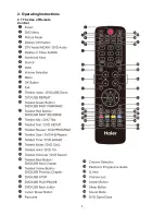
Страница 5: ...5 2 Operating Instructions 2 1 The Use of Remote Control ...

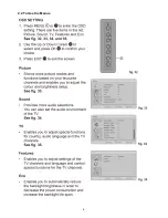
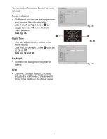
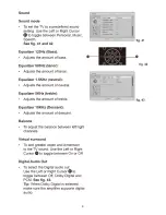
Страница 6: ...6 2 2 To Use the Menus ...

Страница 7: ...7 ...

Страница 8: ...8 ...

Страница 9: ...9 ...

Страница 10: ...10 ...

Страница 11: ...11 ...

Страница 12: ...12 ...

Страница 13: ...13 ...

Страница 14: ...14 ...

Страница 15: ...15 ...

Страница 16: ...16 ...

Страница 17: ...17 ...

Страница 18: ...18 ...

Страница 19: ... to power off RC RESPOND is same as the VARIABLE Remarks 2 Volume maximum level MAXIMUM VOLUME Option 0 60 Default VARIABLE Function The volume cannot be increased more than the value which you set Remarks If you set a maximum volume value the volume bar will not display when you press the VOL key on the remote control until the value reach the maximum value The volume of the headphones or monitor...

Страница 20: ...LAY Option YES NO or LIMITED Default YES Function YES all of the OSD will display NO all of the OSD will not display LIMITED only a little of OSD will display Disabled key NO aspect Sleep Timer Menu EPG Freeze OSD will be disable to display LIMITED only the POWER VOLUME CHANNEL Mute ATV DTV Text OSD are enabled to display In Text text subtitle subpage Reveal hidden Teletext Top Bottom Full hold Mu...

Страница 21: ...to do reset function 11 Hotel mode setting HOTEL MODE Option OFF or ON loop enabled Default OFF Function OFF HOTEL MODE is disabled ON HOTEL MODE is enabled Remarks To active hotel mode 12 TV TO USB Option Press Default Function Press the key to do TV TO USB function it will clone this TV set is setting and channel data to USB disk When finish clone it will display Done Remarks USB flash disk will...

Страница 22: ...22 2 3 How to Connect ...

Страница 23: ...23 ...

Страница 24: ...24 ...

Страница 25: ...25 2 4 Front Panel Control Knobs ...

Страница 26: ...26 ...

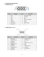
Страница 27: ... Ground 14 V Sync 7 Green Ground 15 Data Clock SCL 8 Blue Ground 3 2 HDMI Digital Connector Pin No Description Pin No Description 1 TMDS Data2 11 TMDS Clock Shield 2 TMDS Data2 shield 12 TMDS Clock 3 TDMS Data2 13 CEC 4 TMDS Data1 14 Reserved N C on device 5 TMDS Data1 shield 15 SCL 6 TMDS Data1 16 SDA 7 TMDS Data0 17 DDC CEC Ground 8 TMDS Data0 shield 18 5V Power 9 TMDS Data0 19 Hot Plug Detect 1...

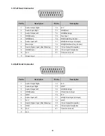
Страница 28: ...itch Signal Input Fast Blanking 19 Video Output Composite 9 GND Green 20 Video Input Composite 10 N C 21 Common Ground 11 Green Input 3 4 Half Scart Connector Pin No Description Pin No Description 1 Audio Output Right 12 N C 2 Audio Input Right 13 GND 3 Audio Output Left 14 GND Blanking 4 GND Audio 15 Chrominance Input 5 GND 16 N C 6 Audio Input Left 17 GND Video Input Output 7 N C 18 GND 8 Switch...

Страница 29: ...ART is not equiped for 19 22 and 26 Audio signal R L input Level Nominal 0 5 V rms Maximum 2 0 V rms Impedance 10 k Ω R L output Level Nominal 0 5 V rms Maximum 2 0 V rms HDMI signal Digital interface with 4 channels TMDS signal HDMI support both AV type and PC DVI 3 5 2 TV signal output Video SCART CVBS output RF out 1Vpp 300mV sync 700mV video SCART CVBS output Monitor out 1Vpp 300mV sync 700mV ...

Страница 30: ...30 3 6 VGA Support Format ...

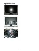
Страница 31: ...31 4 Mechanical Instructions Front view Back view 1 Unplug and remove the base ...

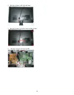
Страница 32: ...32 2 Remove 4 screws to take the neck away 3 Remove 8 screws on the back cover and take it away 4 Remove 7 screws to remove the BKT ...

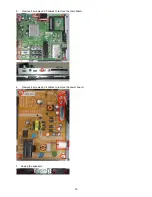
Страница 33: ...33 5 Remove 5 screws and 5 cables to remove the main board 6 Remove 4 screws and 4 cables to remove the power board 7 Unplug the speakers ...

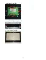
Страница 34: ...34 8 Unplug and remove the IR board 9 Remove 2 screws to romove the key board 10 Separate the panel and the bezel ...

Страница 35: ... key board IR board Check U401 Change U401 Check key board IR board No picture OK NG OK NG Check 24V power supply OK Check the power supply circuit NG Check main board standby power supply Change U751 OK NG Check I2 C bus Check I2 C communication NG OK ...

Страница 36: ... OK OK Change U401 NG Check U601 OK NG Change U601 Check speaker NG Change speaker Check if mute OK OK OK Check TV system setup Reset source Replace the filter or resistance RF signal Check Tuner Replace Tuner Check LVDS cable Check input Replace LVDS cable Check panel Replace panel OK OK NG OK OK NG OK OK NG OK Check signal filter circuit Check the source NG NG NG ...

Страница 37: ... Q901 Q920 D901 D908 D913 NG Replace IC901 OK Check T901 OK Replace T901 NG NG Replace Q901 Q920 D901 D908 D913 NG Check power cord and board interface Plug in power cord and interface OK Check F901 BD901 NG Replace F901 BD901 OK Check IC901 Check Q901 Q920 D901 D915 D910 D908 D913 D923 NG Replace IC901 OK Check T901 OK Replace T901 NG NG Replace Q901 Q920 D901 D915 D910 D908 D913 D923 ...

Страница 38: ...901 OK Check IC901 Check Q901 Q920 D901 D908 D913 NG Replace IC901 OK Check T901 OK Replace T901 NG NG Replace Q901 Q920 D901 D908 D913 Check the source OK Reset source Check LVDS cable NG Reset LVDS cable OK Check Q750 Q7501 NG Replace Q750 Q7501 OK Check U401 NG Replace main board OK Check panel NG Replace panel Check Q401 Q402 NG Replace Q401 Q402 OK NG ...

Страница 39: ...OSD is unstable or not working Is Key Pad Board connecting normally Connect Key Pad Board Is Button Switch normally Replace Button Switch Y Is Key Pad Board Normally Replace Key Pad Board Check Main Board N N Y Y N ...

Страница 40: ...40 6 PCB Layout 6 1 Main Board 715G4035 ...

Страница 41: ...41 ...

Страница 42: ...42 6 2 Power Board 6 2 1 For LT19Z6715 715G3762 ...

Страница 43: ...43 ...

Страница 44: ...44 6 2 2 Power Board For LTF22Z6 LTF24Z6 715G3895 ...

Страница 45: ...45 ...

Страница 46: ...46 715G4313 ...

Страница 47: ...47 ...

Страница 48: ...48 ...

Страница 49: ...49 6 3 Key Board 715G4168 6 4 IR Board 715G4169R01 ...

Страница 50: ...se values to NVM Color temperature Normal Warm Cool x y co ordinates specification Table 5 Reading with Knoica Minolta CS 200 Note 1 Use Knoica Minolta CS 200 for color coordinates and luminance check 2 For suitable mass production at factory colour analyzers CA 210 can be applied But befor measureing all CA 210 should be coordinates and proofread with a Charoma Meter CS 200 or equivalent instrume...

Страница 51: ...mode Turn on the TV press MENU key with remote control then press number key 1 Æ 9 Æ 9 Æ 9 It will achieve the factory mode 2 Click on Auto Color in the PC and COMPONENT models PC mode TIM 137 PAT 42 COMPONENT mode TIM 316 PAT 185 ...

Страница 52: ...52 8 Block Diagram ...

Страница 53: ...53 9 Wiring Diagram ...

Страница 54: ...54 LTF22Z6 Power Board 715G4313 AC IN CN901 To Panel 13 Pin CN906 Power Board 6 Pin CN902 Harness 095G801313X915 Harness 095G801830X914 ...

Страница 55: ...55 LTF24Z6 Power Board 715G4313 715G3798 Power Board Harness 095G801313X915 Harness 095G801830X917 AC IN CN901 13 Pin CN903 6 6 Pin CN902 To Panel Inverter Board 10 Pin CN801 10 Pin CN802 ...

Страница 56: ..._24V_16V 13 C733 100uF 10V R720 2K2 1 10W 1 OPWRSB DV11 C717 100N 16V C718 NC 1500P50V C734 100uF 16V C719 10uF 16V Vout 0 92x 1 2K2 10K2 1 12V for G5657 5V_STB R721 10 2KOHM 1 1 10W FB705 220R 2000mA 1 2 C715 100N 16V D701 SS3P4 1 2 CN701 CONN 1 2 3 4 5 6 7 8 9 10 11 12 13 C713 330UF 16V R714 4 7K1 16W U701 MP9403EN LF Z BS 1 IN 2 SW 3 GND 4 FB 5 COMP 6 EN 7 SS 8 Thermal Pad 9 PWR_12V L701 15uH T...

Страница 57: ...5 6 7 8 9 10 11 12 13 14 5V_STB 2 6 8 AV12 4 5 6 7 12 14 PANEL_VCC 14 AV33 6 12 14 NEARLY TUNER U754 SC4215HSETRT NC 1 EN 2 VIN 3 NC 4 GND 8 FB 7 VO 6 NC 5 TH1 9 R760 20K 1 16W 1 R761 20K 1 16W 1 R752 NC 0R05 4A 1 4W C752 100uF 16V R759 4K7 1 16W 1 5V_TUNER R762 1K 1 16W 1 PWR_12V 5V_TUNER FROM Regulator C753 220UF 16V FB752 220R 2000mA 1 2 SMD C756 100N 16V R767 NC 0R05 1 4W SMD C767 10uF 16V C76...

Страница 58: ...5 10K1 16W M_AOLRCK 9 GND_Tuner C1099 10N 50V R1030 NC 100R 1 16W 5 GND_Tuner R1028 NC 0R05 1 10W C1018 33P 50V C1030 NC 1N 50V C1010 39pF 50V C1000 330uF 10V C1011 39pF 50V Ver B R1059 0R05OHM1 16W R1076 0R05OHM1 16W FB1023 60 OHM 1 2 DV12_VADC C1042 NC 10P 50V Back Front AV12 TUNER_DATA R1036 NC 4 7K1 16W FB1008 120R 3000mA 1 2 SMD 0402 R1037 NC 4 7K1 16W R1019 1K1 16W TCK TSYNC TDO DV33_DVBC TV...

Страница 59: ...6 DVSS W6 DVSS C8 DVSS E8 DVSS G8 DVSS AE8 DVSS D9 DVSS F9 DVSS AF9 DVSS G10 DVSS AB13 DVSS AD13 DVSS N14 DVSS R14 DVSS W14 DVSS AC14 DVSS P15 DVSS T15 DVSS V15 DVSS AB15 DVSS U16 DVSS W16 DVSS AA16 DVSS AC16 DVSS T17 DVSS V17 DVSS Y17 DVSS AB17 DVSS R18 DVSS U18 DVSS W18 DVSS AA18 DVSS AC18 DVSS T19 DVSS V19 DVSS Y19 DVSS AB19 DVSS N20 DVSS R20 DVSS U20 DVSS W20 DVSS AA20 DVSS AC20 DVSS B21 DVSS ...

Страница 60: ...5 M_AOSDATA0 5 M_AOBCK 5 R4051 0R05OHM1 16W Tuner_By Pass_Out 10 Moniter_Out 10 MPX_P 4 MPX_N 4 SCART1_R_In 10 SCART1_L_In 10 VGA_R_In 11 VGA_L_In 11 Audio I F MT5363LIMG U401F AVDD33_REF_AADC W30 AVSS33_REF_AADC Y29 VMID_AADC AA30 AVDD33_AADC Y31 AVDD33_ADAC1 T31 AVSS33_ADAC1 U30 AIN4_R_AADC AB33 AIN0_L_AADC AD33 AL2 V35 AVSS33_AADC Y33 AIN1_R_AADC AC32 AIN0_R_AADC AC34 AL3 V37 AIN4_L_AADC AA32 A...

Страница 61: ...RVREF1 C4121 100N 16V SMD 0402 RP4100 56R 1 16W 5 1 2 3 4 8 7 6 5 C4122 100N 16V C4123 100N 16V R4107 100OHM1 16W C4124 100N 16V C4130 10N 50V RDQ2 RDQ1 RDQ4 RDQ0 RDQ5 RDQ6 RDQ7 RDQ3 RDQ14 RDQ15 RDQS1 1_CKE RDQS0 C4125 100N 16V RDQ11 RDQ12 RDQ8 RDQ13 RDQ9 RDQS0 RDQS1 RVREF1 RDQM0 RDQM1 RDQ10 NEAR DRAM NEAR DRAM R4109 22 OHM 1 16W DV18_DDR DV18_DDR RP4110 56R 1 16W 5 1 2 3 4 8 7 6 5 DDR 2 SMD 0402 ...

Страница 62: ...NC 26 NC 27 NC 28 I O0 29 I O1 30 I O2 31 I O3 32 NC 33 NC 34 NC 35 VSS 36 VCC 37 PRE 38 NC 39 NC 40 I O4 41 I O5 42 I O6 43 I O7 44 NC 45 NC 46 NC 47 NC 48 HI WRITE LO WP I2C ADDRESS A0 DV33 DV33 DV33 DV33 U409 M24C32 WDW6 E0 1 E1 2 E2 3 VSS 4 SDA 5 SCL 6 WC 7 VCC 8 R4180 100K1 16W ORESET VCXO PAALE R4156 100OHM1 16W R4172 100R 1 10W 1 R4182 4 7K1 16W R4175 100R 1 10W 1 PDD4 C4159 100N 50V C4160 ...

Страница 63: ...25 GPIO18 D27 GPIO19 G26 GPIO20 E26 GPIO21 A26 GPIO14 G28 GPIO15 H27 GPIO16 F27 GPIO17 B27 GPIO10 D29 GPIO11 C28 GPIO12 E28 GPIO13 J28 GPIO6 E30 GPIO7 H29 GPIO8 F29 GPIO9 B29 GPIO3 A30 GPIO4 C30 GPIO5 G30 ETPHYCLK F31 ETTXD3 B31 ETTXEN D31 ETCOL G32 ETTXD0 A32 ETTXD1 C32 ETTXD2 E32 ETRXCLK B33 ETTXCLK D33 CI_MCLKO F33 CI_MISTRT H33 ETRXD2 A34 ETRXD3 C34 ETTXER E34 CI_MIVAL G34 ETRXD1 B35 ETRXER D3...

Страница 64: ... R1092 47K1 10W R1054 330 OHM 1 10W ZD1070 NC VPORT0603100KV05 1 2 SMD 0402 Audio_Line_Out_L C1076 10uF 16V Audio_Line_Out_R R1075 47K1 10W C1122 10N 50V R1050 NC 47K1 16W U107 RC4580IPWR 1OUT 1 1IN 2 1IN 3 VCC 4 2IN 5 2IN 6 2OUT 7 VCC 8 R1069 330 OHM 1 10W SMD 0402 R1082 5K1 1 16W 5 R1 Q1056 DTC623TK 2 3 1 ZD1072 NC VPORT0603100KV05 1 2 R1086 0R05OHM1 16W 12V OFF_MUTE C1087 820PF 50V OFF_MUTE HP_...

Страница 65: ... 3V VGASDA_IN A B C CN136 JACK 2 1 4 3 5 6 R1174 75OHM1 16W R1156 0R05OHM1 16W R1178 68OHM 1 16W RC_BLANK D1160 BAS316 A 1 K 2 C1171 5PF 50V C1161 100N 50V C1158 5PF 50V VGA_AudioRIN VGA_AudioLIN SMD 0402 C1164 10uF 16V R1162 100OHM1 16W R1152 30KOHM 1 16W 5 C1173 1 5nF 50V Y_IN_1 GRN R1181 100OHM1 16W R1169 56R 1 16W 1 R1161 56R 1 16W 1 C1159 10N 50V C1174 10uF 6 3V M_OPCTRL3 5 8 12 C1170 5PF 50V...

Страница 66: ...X2_1 RX2_2 RX2_1 RX2_2 HDMI2_SDA HDMI2_SCL PWR5V_2 HPD2 R543 NC 4K7 1 16W 5 The item of this page start from 501 SMD 0402 RX1_2 USB_DP 6 RX1_1 RX1_1 RX1_2 RX2_C RX2_C RX2_0 R562 5K1 1 16W 5 PWR5V_2 SCL_1 SDA_1 PWR5V_1 PWR5V_1 RX1_1 RX1_1 RX1_2 RX1_2 CEC_1 RX1_C RX1_C RX1_0 RX1_0 HDMI 1 INPUT SCL_2 CEC_2 PWR5V_2 ZD503 VPORT0603100KV05 1 2 SDA_2 SCL_2 RX2_0 RX2_1 RX2_1 RX2_2 RX2_2 R530 NC 0R05OHM1 1...

Страница 67: ...35V FB612 120R 3000mA 1 2 FB613 120R 3000mA 1 2 FB614 120R 3000mA 1 2 FB615 120R 3000mA 1 2 GND_SOUND FB602 120R 3000mA 1 2 FB603 120R 3000mA 1 2 FB611 120R 3000mA 1 2 FB604 120R 3000mA 1 2 ROUT C636 1N 50V R652 R620 10K1 16W SMD 0402 DV33 C638 1N 50V GND_SOUND GND_SOUND C606 0 47uF 16V Line_Out_R C628 220NF 25V C604 330UF 35V DV33 SMD 0402 OFF_MUTE SD 24K 1 LOUT GND_SOUND ROUT SMD 0402 C615 1U 25...

Страница 68: ... Q402 LMBT3904LT1G 3 1 2 DV33 DV33 DV33 5V_SW 5V_SW DV33 INVERTER ON OFF BackLight_SW BackLight on Low BackLight off High BRIGHT ADJUST BRIGHT_ADJ ECKN ECKP E3N E3P OCKP OCKN SMD 0402 TP420 1 TP410 1 TP421 1 TP411 1 SMD 0402 SMD 0402 TP403 1 TP402 1 FB403 NC 120R 3000mA 1 2 FB402 120R 3000mA 1 2 O2N O2P Dual signal Single Signal O0N OCKP OCKN FB406 120R 3000mA 1 2 O1N C407 330UF 16V TP401 1 C403 1...

Страница 69: ...M 1 4W C912 470uF 16V L901 Coil C913 100N 50V R903 100K 1 4W C923 22N 25V R926 3K9 1 8W 1 R931 2K43 1 8W 1 R916 47 OHM 1 4W L903 15mH 1 4 2 3 C908 0 1NF2KV Q901 STP10NK70ZFP C911 470uF 10V R910 3 3K 1 4W R914 22 OHM 1 8W D909 PR1007 IC901 LD7576 CT 1 COMP 2 CS 3 GND 4 OUT 5 VCC 6 NC 7 HV 8 R925 43K 1 8W 1 D910 SR506 C916 47N 50V C920 1nF50V R909 100K 1 4W C905 68UF 25V C919 0 001uF 250V R908 100K ...

Страница 70: ... 1 R0805 IC905 KIA431A AT P R940 1K 1 8W R952 1K 1 8W 1 42 9V D916 BAW56 3 2 1 D918 BAW56 3 2 1 R937 10KOHM 5 1 8W Q917 2N3904 R953 75R 1 8W 1 R956 10KOHM 5 1 8W Q910 2N3904 C943 100N 50V R958 100KOHM 5 1 8W VCC R949 12K 1 8W 1 R0805 R978 10ohm 1 1 8W C940 100N 50V C936 470NF 25V 1 2 R905 1K 1 8W C904 1N 50V Q920 AO4438 S 1 S 2 S 3 G 4 D 8 D 7 D 6 D 5 R951 0 05 OHM 5 2WS R942 10KOHM 5 1 8W Q918 2N...

Страница 71: ... 50V C920 1nF50V R909 100K 1 4W C905 68UF 25V C919 470pF 250V R908 100K 1 4W C917 47UF 35V IC903 KIA431A AT P 56G 158 12 IC902 PC123X2YFZOF 56G 139 3A 1 2 4 3 C918 100N 50V R929 2K 1 8W 5 R924 3K3 5 1 8W C901 2N2 500V R906 3 3K 1 4W R912 2 2 OHM 1 4W CN903 CONN L 1 N 2 R918 220R 1 8W 5 D911 1N4148 B4006 C914 2N2 500V R904 100K 1 4W C910 470pF 250V R913 3 3K 1 4W L902 Coil C915 C921 680pF t NR901 N...

Страница 72: ... 8W R0805 R946 1 6K 1 R0805 R947 NC R0805 R948 12K 1 8W 1 R0805 IC905 KIA431A AT P L904 100UH R940 1K 1 8W R952 1K 1 8W 1 42 9V D916 BAW56 3 2 1 D918 BAW56 3 2 1 C944 120UF 63V R937 10KOHM 5 1 8W Q917 2N3904 R953 75R 1 8W 1 R956 10KOHM 5 1 8W Q910 2N3904 R958 100KOHM 5 1 8W R949 12K 1 8W 1 R0805 R978 10ohm 1 1 8W C940 100N 50V C936 470NF 25V 1 2 2 5V R905 1K 1 4W C904 1N 50V Q920 AO4438 S 1 S 2 S ...

Страница 73: ...50V R908 100K 1 4W C922 470pF 250V C916 22UF 35V R907 100K 1 4W IC903 KIA431A AT P 56G 158 12 C917 100N 50V 1 2 4 3 IC902 PC123X2YFZOF 56G 139 3A R925 2K 1 8W 5 R919 3K3 5 1 8W C901 1N 500V R906 3 3K 1 4W R910 2 2 OHM 1 4W L 1 N 2 CN901 CONN R916 220R 1 8W 5 C914 2N2 500V D904 NC R905 100K 1 4W C923 470pF 250V R911 3 3K 1 4W C919 0 47UF L902 Coil 1 2 t NR901 NTCR C925 NC R913 10K 1 8W R915 100 OHM...

Страница 74: ... 330 OHM 1 1 8W Short LED protector R945 12K 1 8W 1 DC DC Converter Compensation circuit IC905 KIA431A AT P L904 100UH R932 6 2K 1 8W R940 1K 1 8W 1 60V LED12 R9102 0R01 1 10W R935 10KOHM 5 1 8W Q903 2N3904 R949 75R 1 8W 1 R9103 NC R961 NC R9104 NC LED14 Q916 NC R9105 NC R985 100KOHM 5 1 8W R962 10ohm 1 1 8W C937 100N 50V 1 2 C933 470NF 25V R9106 0R01 1 10W R958 R9107 0R01 1 10W 2 5V R936 1K 1 8W ...

Страница 75: ...50V SW020 TACT SW FWRD H1 5MM SW017 TACT SW FWRD H1 5MM VOL VOL SW018 TACT SW FWRD H1 5MM CH CH R017 4 3KOHM 5 1 10W R018 1 8KOHM 5 1 10W R019 470 OHM 5 1 10W R016 11KOHM 5 1 10W KEY2 SW021 TACT SW FWRD H1 5MM R020 1 8K OHM 1 10W 5 R021 4K3 1 10W 5 R022 11KOHM 5 1 10W SW022 TACT SW FWRD H1 5MM C016 NC 100N 50V C017 NC 100N 50V C018 NC 100N 50V SW016 TACT SW FWRD H1 5MM INPUT MENU POWER ...

Страница 76: ...76 10 4 IR Board 715G4169 IRRV 33G8032 4F HR C201 0 1uF 16V VCC R201 15K 1 10W ZD1151 VPORT0603100KV05 1 2 CN201 CONN 1 2 3 4 6 5 IRRV U201 IRM 3638TF16 VS 3 OUT 1 GND 2 ...

Отзывы: